Method for deposition tool cleaning

Inactive Publication Date: 2000-05-30
IBM CORP
View PDF33 Cites 43 Cited by
  • Summary
  • Abstract
  • Description
  • Claims
  • Application Information

AI Technical Summary

Benefits of technology

According to the present invention, a method of cleaning a deposition tool is provided to control and minimize emission of environmentally deleterious materials. The method includes the steps of: a) establishing a predetermined temperature in a processing chamber of a deposition tool; b) providing a mixture of between 15 and 25 percent nitrogen trifluoride in inert gas at a mixture flow rate of more than 200 standard cubic centimeters per minute (sccm); c) establi

Problems solved by technology

The film that builds up on the tool or other equipment surfaces may easily degrade cleanliness and lead to defects in the component.
As discussed above, the reaction product (deposition material) also deposits on the walls of the chamber and other equipment therein, creating a potentially deleterious film.
Unfortunately, PFCs are have been found to contribute to global warming and C.sub.2 F.sub.6 has a long atmospheric life of more than 10,000 years.
Destruction and recycling have been somewhat successful in reducing PFCs without impact on the cleaning process, nevertheless, such options require significant and costly modifications to existin

Method used


Image

  • Method for deposition tool cleaning
  • Method for deposition tool cleaning
  • Method for deposition tool cleaning

Examples


Example

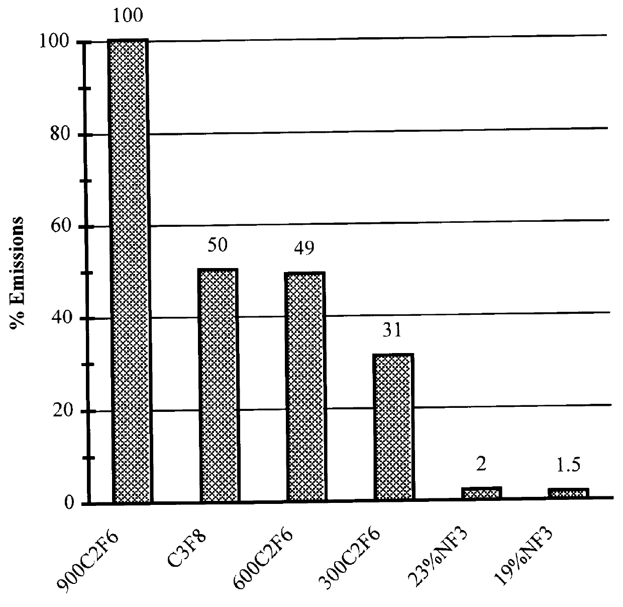
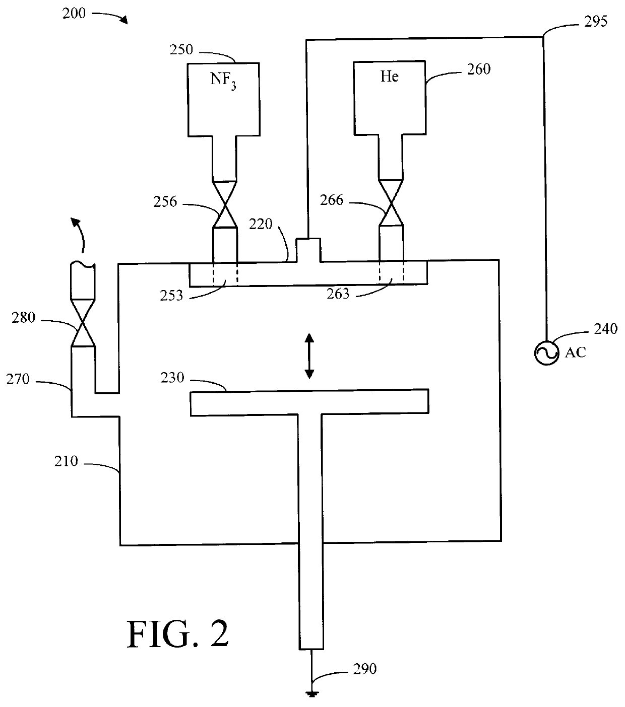
A silicon wafer was coated with approximately 1000 Angstroms (.ANG.) of SiO.sub.2 using O.sub.2 gas with a tetraethylorthosilicate (TEOS) precursor and placed in the deposition chamber of an AME P5000 PECVD deposition tool in preparation for a first run termed "Clean A". A susceptor temperature of 400.degree. C. was established at a susceptor spacing of 200 mils (5.08 millimeters (mm)) (closest setting to face plate) and flows of 138 sccm NF.sub.3 and 590 sccm He were provided to produce 19% NF.sub.3 in He. While maintaining susceptor temperature, a high pressure of 9.5 torr was established in the deposition tool and 950 W of generator RF power provided for 15 seconds (sec) to generate a localized plasma and perform the inner clean. Susceptor spacing was changed to 999 mils (25.4 mm) (farthest setting from face plate). While maintaining susceptor temperature, a low pressure of 1.5 torr was established in the deposition tool and 950 W applied for 30 sec to generate a generalized plas...


PUM

PropertyMeasurementUnit
Fractionaaaaaaaaaa
Fractionaaaaaaaaaa
Fractionaaaaaaaaaa

Abstract

A method of cleaning a deposition tool to control and minimize emission of environmentally deleterious materials includes the steps of: a) establishing a predetermined temperature in a processing chamber; b) providing a mixture of between 15 and 25 percent nitrogen trifluoride in helium at a mixture flow rate of more than 550 standard cubic centimeters per minute (sccm); c) establishing a high pressure of 1.5 to 9.5 torr in the processing chamber; d) establishing a plasma in the processing chamber, e) establishing a low pressure in the processing chamber of 2 torr or less; and f) establishing a plasma in the processing chamber. Instead of a two-step cleaning method, the method may alternatively be executed as a one-step cleaning method. Either method may be optimized by, among other things, providing 19% nitrogen trifluoride. The two-step method may also be optimized by providing a high pressure of about 7 to 9.5 torr and a low pressure of about 1.5 torr.

Description

1. Technical FieldThis invention relates to the field of deposition tool cleaning. More specifically, the invention relates to a method for cleaning plasma enhanced chemical vapor deposition (PECVD) tools.2. Background ArtIn the electronics industry, various techniques have been developed whereby selected materials, such as, conductors, insulators, or semiconductors, may be deposited on a substrate. For example, such techniques are often used to deposit successive conductive, semi-conductive, or insulative layers on a silicon wafer in the production of an integrated circuit (IC). Generally, deposition techniques result in a film of deposition materials collecting on surfaces other than the target substrate, that is, the deposition materials also collect on the tool surfaces or other equipment used in the deposition process. In many electronic component fabrication processes, a very clean environment is required to produce components of acceptable quality. The film that builds up on ...

Claims


Application Information

Patent Timeline
IPC IPC(8): C23C16/44
CPCC23C16/4405
Inventor HINES, CYNTHIA MARIEPINTO, JAMES NICHOLAS
Owner IBM CORP
Why Eureka
Try Eureka