Hemispherical test head for integrated circuit tester employing radially distributed circuit cards

a technology of integrated circuit tester and radially distributed circuit card, which is applied in the direction of individual semiconductor device testing, semiconductor/solid-state device testing/measurement, instruments, etc., can solve the problems of increasing the time required to program the tester, limiting the speed with which an ic tester can be programmed for a test, and impracticality of using centralized vector memory

Inactive Publication Date: 2000-06-20
CREDENCE SYSTEMS
View PDF4 Cites 31 Cited by
  • Summary
  • Abstract
  • Description
  • Claims
  • Application Information

AI Technical Summary

Benefits of technology

to provide a test head structure for holding large numbers of nodes cards of a per-pin ...

Problems solved by technology

Due to the large number of parallel buses needed to transmit the vectors concurrently to the pin electronics, the use of a centralized vector memory has become impractical.
While Brune's system reduces the amount of wiring in a tester, it increases the time required to program the tester.
Since each vector memory must store one vector for each cycle of the test, the number of vectors that must be distributed to the vector memories can be so enormous that band width limitations on the computer bus greatly limit the speed with which an IC tester can be programmed for a test.
Signal delay becomes problematic when we employ distributed instruction processors in a large circuit tester.
Signal delay is critical when testing an integrated circuit because test activities at all nodes must be precisely coordinated.
As we increase the complexity of the tester nodes, we also increase the physical size of the nodes and it becomes more difficult to keep all nodes close to the device ...

Method used


Image

  • Hemispherical test head for integrated circuit tester employing radially distributed circuit cards
  • Hemispherical test head for integrated circuit tester employing radially distributed circuit cards
  • Hemispherical test head for integrated circuit tester employing radially distributed circuit cards

Examples


Embodiment Construction

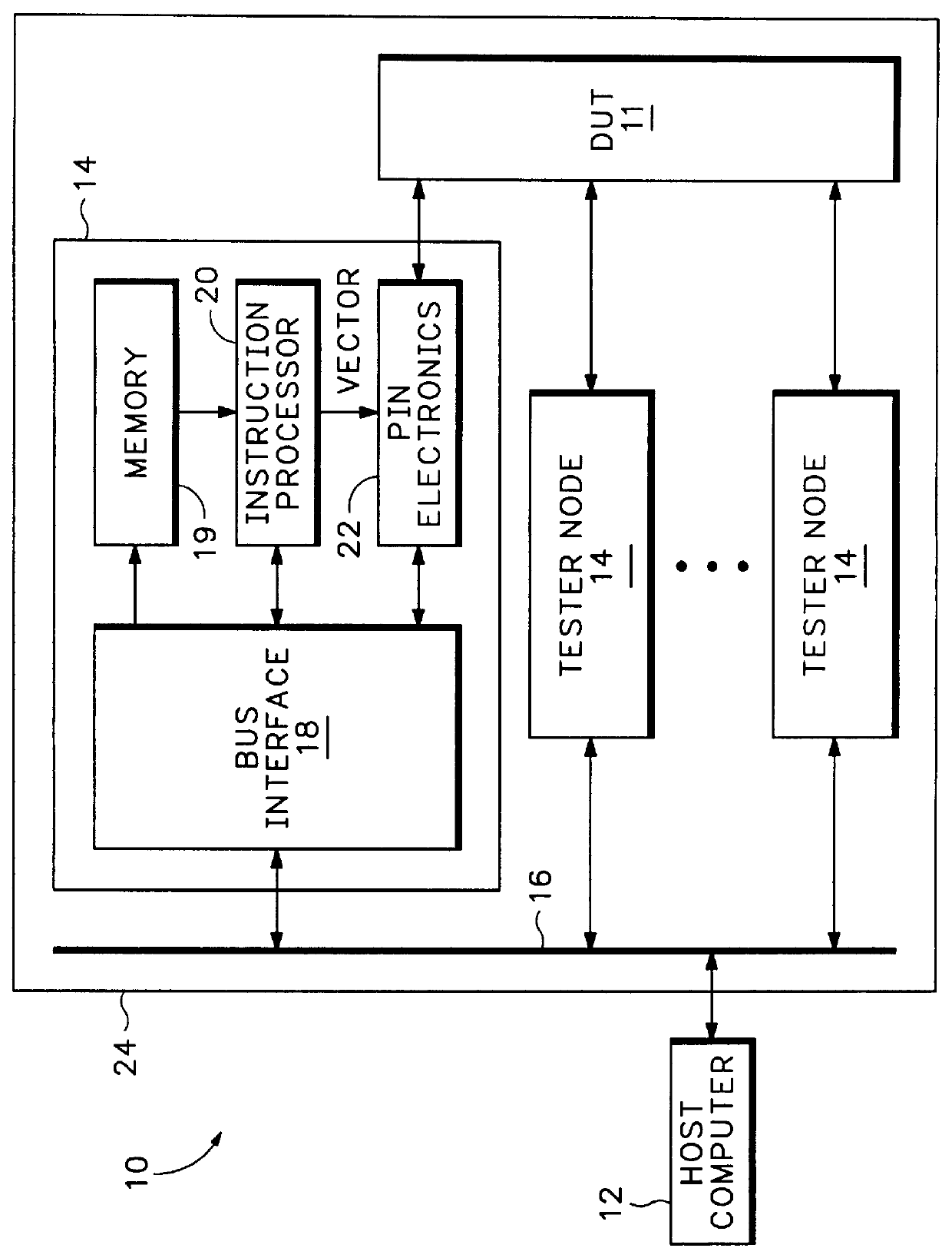
FIG. 1 is an electronic block diagram of a per-pin integrated circuit tester 10 for testing an integrated circuit device under test (DUT) 11. Tester 10 includes a host computer 12 connected to a set of tester nodes 14 via a bus 16. Each tester node 14 includes a bus interface circuit 18, a memory 19, an instruction processor 20, and a pin electronics circuit 22. During a test of DUT 11, the pin electronics circuit 22 of each tester node 14 carries out all test activities with respect to a corresponding terminal of DUT 11. For example at various times during a test, a pin electronics circuit 22 may transmit a test signal of a particular logic level to the DUT terminal or may sample the state of output signal produced by DUT 11 at the DUT terminal and store data indicating the results in internal acquisition memories. The actions of the pin electronics circuit 22 of each node 14 are controlled by an input sequence of data (test vectors) produced by the node's instruction processor 20 ...


PUM


Abstract

A test head for an integrated circuit tester includes a set of wedge-shaped node cards, one for each terminal of the integrated circuit device under test (DUT). Each node card holds circuits for carrying out all test activities at one DUT terminal including generating and transmitting a test signal to the DUT and receiving and processing a response signal produced by the DUT. The test and response signals pass through an I/O terminal at a narrow end of the node card. A card frame having hemispherical inner and outer shells holds the node cards substantially therebetween with the I/O terminal of each card protruding through an aperture in the inner shell. A centroid distributor having substantially a hemispherical shaped surface nesting within the inner shell of the card frame holds a set of first terminals in contact with the node card I/O terminals. A set of conductors within the centroid distributor interconnect each first terminal with a corresponding second terminal on a flat surface of the distributor. A load board assembly holds the DUT and a connector assembly links each second terminal of the centroid distributor to a contact on the load board providing access to a DUT terminal. A pump evacuating air from a space between the inner shell of the card frame and the centroid distributor draws cooling air across the node cards.

Description

1. Field of the InventionThe present invention relates in general to equipment for automatically testing electronic circuits and in particular to a test head structure for holding components of a per-pin integrated circuit tester.2. Description of Related ArtAn integrated circuit tester applies patterns of logic signals to input terminals of an integrated circuit (IC) and acquires the resulting logic signal patterns produced at its output terminals. Testers typically include a separate "pin electronics" circuit for each IC terminal. During each cycle of a test, a pin electronics circuit can, for example, send a high or low logic level test signal to the pin, sample an IC output signal at the pin and store data indicating its logic level, or do nothing. The action each pin electronics circuit takes during a given test cycle is controlled by the value of input data (a "test vector") supplied thereto at the start of the cycle. A test vector may also include timing data that tells the p...

Claims


Application Information

Patent Timeline
IPC IPC(8): G01R31/319G01R31/28G01R31/26G01R1/067H01L21/66
CPCG01R31/2886G01R31/31905G01R31/2891G01R31/2851G01R31/2889
Inventor HANNERS, JOHN C.MILLER, CHARLES A.
Owner CREDENCE SYSTEMS
Why Eureka
Try Eureka