Method and apparatus for adjusting overflow buffers and flow control watermark levels

a flow control and buffer technology, applied in the field of network switching, can solve problems such as data packet loss, network congestion, data packet loss,

Inactive Publication Date: 2000-07-04
GLOBALFOUNDRIES INC
View PDF7 Cites 163 Cited by
  • Summary
  • Abstract
  • Description
  • Claims
  • Application Information

AI Technical Summary

Problems solved by technology

Network congestion occurs if a receiving network element, for example a receiving network station, is unable to receive data at a rate greater than or equal to the transmission rate of the transmitting element.
If the number of client requests exceeds the capacity of the server's port, some of the data packets will be lost.
In another example, a client having limited buffer space may be unable to keep up with the transmission rate of a transmitting station, resulting in lost packets.
Finally, network congestion may occur if a transmitting station attempts to transmit data packets to a receiving station that is already receiving data packets from another transmitting station.
Hence, a receiving station may be unable to keep up with reception of data packets from two separate transmitting stations.
The disclosed flow control proposals, however, assume that flow control should be initiated when a receive buffer is full, which still results in a loss of data.
Moreover, the existing proposals do not describe how to determine the instance in which flow control should be initiated.
The problem also becomes more complex in a switched environment, where a network switch must route data packets received from a plurality of transmitting stations to the appropriate destination stations.
Moreover, if the flow control duration is too short, a receiving station may still lose portions of the transmitted data.
If the duration is too long, the transmitting station remains idle, reducing network throughput.
A more fundamental problem is that a network switch tends to have buffers having fixed sizes.
Hence, the network switch is incapable of accommodating changes in network traffic due to dynamic characteristics within the network.
The buffers of an idle station would be underutilized, whereas the buffers of a busy station would tend to become overloaded, requiring flow control to reduce congestion of the overloaded buffers.
Hence, the necessity of flow control reduces the bandwidth efficiency of the network, and the use of network ports having predetermined buffer sizes increases the risk of dropped frames on overloaded network ports, while buffers on idle ports remain unutilized.

Method used


Image

  • Method and apparatus for adjusting overflow buffers and flow control watermark levels
  • Method and apparatus for adjusting overflow buffers and flow control watermark levels
  • Method and apparatus for adjusting overflow buffers and flow control watermark levels

Examples


Embodiment Construction

The present invention will be described with the example of a switch in a packet switched network, such as an Ethernet (IEEE 802.3) network. A description will first be given of the switch architecture, followed by the arrangement for regulating network activity according to the present invention. It will become apparent, however, that the present invention is also applicable to other packet switched systems, as described in detail below.

SWITCH ARCHITECTURE

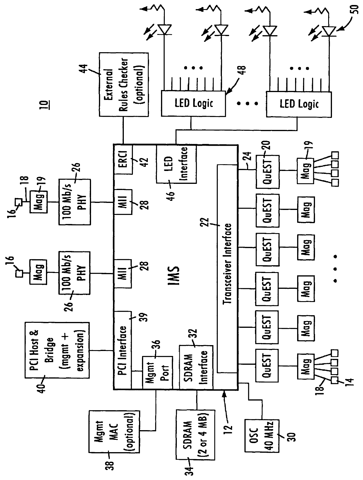
FIG. 1 is a block diagram of an exemplary system in which the present invention may be advantageously employed. The exemplary system 10 is a packet switched network, such as an Ethernet network. The packet switched network includes an integrated multiport switch (IMS) 12 that enables communication of data packets between network stations. The network may include network stations having different configurations, for example twenty-four (24) 10 megabit per second (Mb / s) network stations 14 that send and receive data at a network dat...


PUM


Abstract

A network switch having a shared memory architecture for storing data frames includes configuration registers that are programmable by a host processor to adaptively adjust overflow buffer locations and flow control watermark levels based on monitored network traffic. The host processor allocates shared resources by setting memory configuration registers corresponding to an external memory, where the network switch uses the external memory for storing received data frames, Management Information Base (MIB) counter values, and output port overflow data. The host processor periodically reads the MIB counter values from the external memory, and adjusts flow control watermark levels or the memory configuration registers in the network switch based on rate-based network traffic derived from the MIB counter values. PCI burst transfers between the host processor and the external memory via the network switch ensure that stored data is not lost during reconfiguration of the external memory. The disclosed arrangement enables resources used by the network switch to be adjusted to minimize congestion by borrowing resources from network ports serving idle stations.

Description

1. Technical FieldThe present invention relates to network switching and more particularly, to methods and systems controlling network data traffic on half-duplex and full-duplex media in switched networks.2. Background ArtSwitched local area networks use a network switch for supplying data frames between network stations, where each network station is connected to the network switch by a media. The switched local area network architecture uses a media access control (MAC) enabling network interface cards to access the media. The network switch passes data frames received from a transmitting station to a destination station based on the header information in the received data frame.Network congestion occurs if a receiving network element, for example a receiving network station, is unable to receive data at a rate greater than or equal to the transmission rate of the transmitting element. For example, traffic in a client-server environment is dominated by client requests followed by...

Claims


Application Information

Patent Timeline
Patent Type & Authority Patents(United States)
IPC IPC(8): H04L12/56H04L1/16H04L1/18
CPCH04L49/351H04L49/90H04L1/18H04L47/10H04L49/103H04L49/3027H04L49/354
Inventor SIMMONS, PHILIPDE MONG, ROBERT
Owner GLOBALFOUNDRIES INC
Why Eureka
Try Eureka