Throttle valve providing enhanced cleaning

a valve body and valve body technology, applied in the field of vacuum processing chambers, can solve the problems of inability to achieve symmetry, and inability to achieve uniformity

Inactive Publication Date: 2000-07-18
APPLIED MATERIALS INC
View PDF27 Cites 39 Cited by
  • Summary
  • Abstract
  • Description
  • Claims
  • Application Information

AI Technical Summary

Benefits of technology

In one aspect of the present invention, a throttle valve assembly is provided, including a throttle valve housing having a bore therethrough and a throttle valve plug assembly. The throttle valve plug assembly includes a shaft rotatably mounted on the throttle valve housing and a throttle valve plug having a concave cut-out portion. The throttle valve plug is mounted on the shaft within the throttle valve housing and substantially perpendicular to the bore. The throttle valve plug has at least two fully open positions and a closed position.

Problems solved by technology

A non-uniform gas flow pattern causes undesirable variations in the uniformity of the coating layer deposited across the surface of the wafer.
Typically the exhaust port opening extending from the process chamber to the vacuum pump leads to asymmetry in the gas flow pattern.
However, in many configurations, symmetry is not possible because complete encirclement of the wafer is not possible due to interfering structures, e.g., the wafer insertion opening through which a robot arm passes the wafer into the chamber.
Such chambers having mechanical asymmetry cannot achieve as high a gas flow symmetry as would be desired on the wafer.
Volatile contaminants which are maintained in their vapor state under the high temperatures of an active processing chamber can and do undesirably condense on the walls of the cool vacuum piping at some distance from the processing area of the processing chamber, but still within the containment limit of the processing chamber defined by the vacuum valve.
During no-flow conditions, these contaminants can migrate back into the processing part of the chamber to undesirably contribute to its contamination.
Cleaning interferes with normal production processing.

Method used


Image

  • Throttle valve providing enhanced cleaning
  • Throttle valve providing enhanced cleaning
  • Throttle valve providing enhanced cleaning

Examples


Embodiment Construction

Illustrative embodiments of the invention are described below. In the interest of clarity, not all features of an actual implementation are described in this specification. It will of course be appreciated that in the development of any such actual embodiment, numerous implementation-specific decisions must be made to achieve the developers' specific goals, such as compliance with system-related and business-related constraints, which will vary from one implementation to another. Moreover, it will be appreciated that such a development effort might be complex and time-consuming, but would nevertheless be a routine undertaking for those of ordinary skill in the art having the benefit of this disclosure.

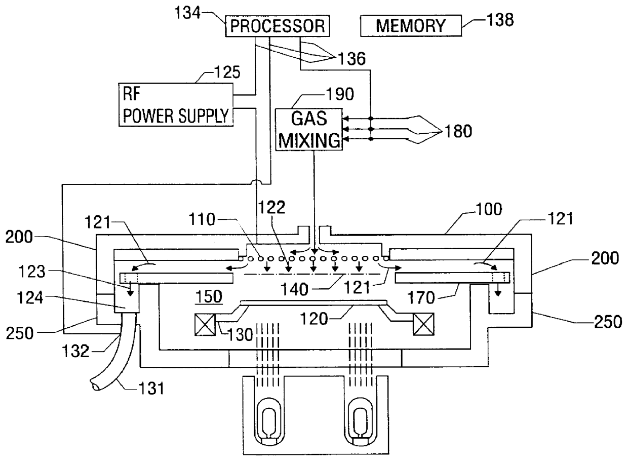
Turning now to the drawings, and in particular to FIG. 1, an exemplary CVD reactor system is shown. Such a CVD reactor system may be suitable for depositing a germanium-doped boron phosphorus silicate glass (BPSG) layer, for example. Such a layer may be formed in a variety of different...


PUM

PropertyMeasurementUnit
angleaaaaaaaaaa
diameteraaaaaaaaaa
diameteraaaaaaaaaa

Abstract

A throttle valve assembly is provided, including a throttle valve housing having a bore therethrough and a throttle valve plug assembly. The throttle valve plug assembly includes a shaft rotatably mounted on the throttle valve housing and a throttle valve plug having a concave cut-out portion. The throttle valve plug is mounted on the shaft within the throttle valve housing and substantially perpendicular to the bore. The throttle valve plug has at least two fully open positions and a closed position.

Description

1. Field of the InventionThis invention relates generally to vacuum processing chambers which are widely used in the semiconductor industry, and in particular to chemical vapor deposition (CVD) processing chambers.2. Description of the Related ArtThe process of depositing layers on a semiconductor wafer (or substrate) usually involves heating the substrate and holding it a short distance from the source of a stream of deposition (or process) gas flowing towards the substrate. The flowing gas reacts and deposits a layer on the heated substrate.A non-uniform gas flow pattern causes undesirable variations in the uniformity of the coating layer deposited across the surface of the wafer. Typically the exhaust port opening extending from the process chamber to the vacuum pump leads to asymmetry in the gas flow pattern. In an attempt to restore symmetry many designs provide a pumping channel which surrounds the wafer. However, in many configurations, symmetry is not possible because comple...

Claims


Application Information

Patent Timeline
Patent Type & Authority Patents(United States)
IPC IPC(8): F16K5/00F16K5/12C23C16/455C23C16/511F16K3/24F16K5/04F16K51/00H01L21/31
CPCF16K5/12
Inventor BANG, WON B.LOSEY, MATTHEW W.CAMPANA, FRANCIMARNEMANI, SRINIVASPICHAI, SUNDAR
Owner APPLIED MATERIALS INC
Why Eureka
Try Eureka