Corrosion resistant steel cords and pneumatic tires reinforced with same

a technology of steel cords and rubber articles, which is applied in the direction of tyre parts, yarn, transportation and packaging, etc., can solve the problems of reducing the durability of cords, reducing the durability of rubber articles such as tires, and reducing so as to reduce the resistance to corrosion fatigue and increase the tensile strength of steel filaments. the effect of the cord

Inactive Publication Date: 2000-08-15
BRIDGESTONE CORP +1
View PDF9 Cites 25 Cited by
  • Summary
  • Abstract
  • Description
  • Claims
  • Application Information

AI Technical Summary

Benefits of technology

It is, therefore, an object of the invention to provide steel cords for use in rubber articles, particularly carcass or belt of a pneumatic tire which can avoid

Problems solved by technology

However, if it is intended to increase the tensile strength per unit section area of a steel filament constituting the steel cord, the weight reduction of the tire is realized, but the resistance to corrosion fatigue is degraded.
Hence there is caused a problem that the durability of the cord and hence the durability of the rubber article such as tire or the like are lowered.
That is, the tire may be sometimes subjected to cut failure arriving at the vicinity of the steel cord through protrusions and foreign matter on a road surface or a roadside edge and hence the steel filaments con

Method used


Image

  • Corrosion resistant steel cords and pneumatic tires reinforced with same
  • Corrosion resistant steel cords and pneumatic tires reinforced with same
  • Corrosion resistant steel cords and pneumatic tires reinforced with same

Examples


Embodiment Construction

Various steel filaments having diameters and tensile strengths shown in Tables 1.about.4 are produced by subjecting a steel wire (diameter: 5.5 mm) having C: 0.70-0.85% by weight, Si: 0.23% by weight, Mn: 0.49% by weight, P: 0.006% by weight and S: 0. 008% by weight to dry drawing, patenting, brass plating and wet drawing in this order.

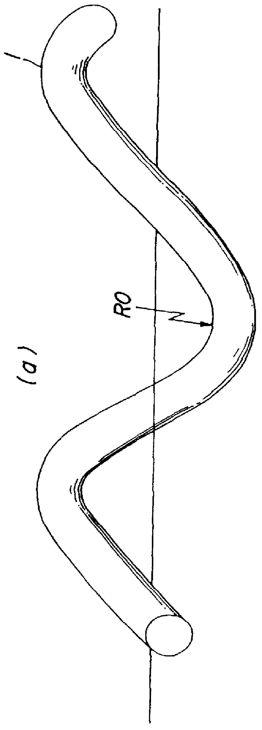
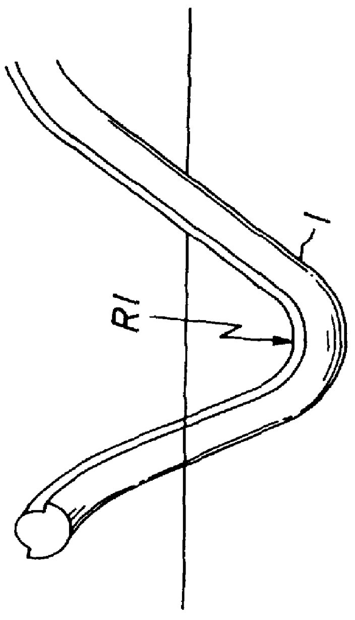
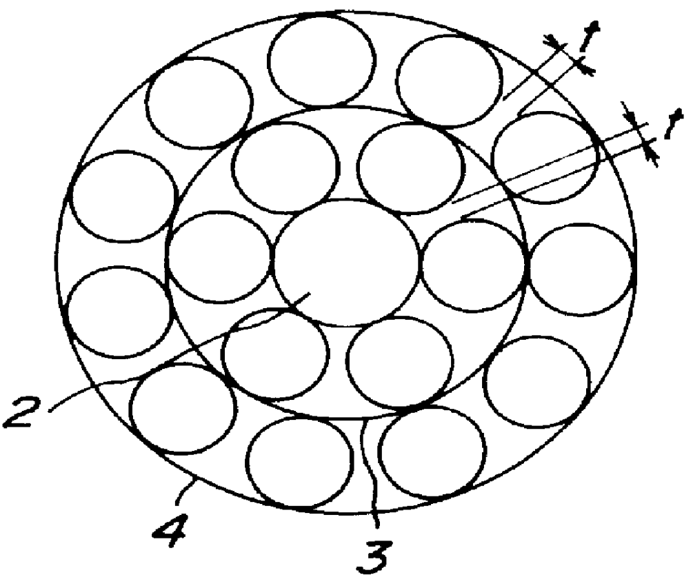
Then, steel cords having various constructions shown in Tables 1-4 are produced by usual manner using a tubular twisting machine or a buncher twisting machine. The steel cord produced in the tubular twisting machine is subjected to such a treatment that in order to reduce the residual tensile stress in the inside of the helix of the steel filament constituting the steel cord, two or more straightening rollers having a large diameter are arranged in zigzag form and the steel cord is passed through these straightening rollers under a tensile stress higher than usual level. On the other hand, when the steel cord is produced by using the buncher twisting ...


PUM

PropertyMeasurementUnit
Fractionaaaaaaaaaa
Fractionaaaaaaaaaa
Percent by massaaaaaaaaaa

Abstract

PCT No. PCT/JP97/01338 Sec. 371 Date Nov. 24, 1997 Sec. 102(e) Date Nov. 24, 1997 PCT Filed Apr. 18, 1997 PCT Pub. No. WO97/39176 PCT Pub. Date Oct. 23, 1997A corrosion resistant steel cord for reinforcing rubber articles, particularly a belt and/or carcass of a pneumatic tire, has a residual compressive stress inside the twisting helix of each steel filament such that a ratio R1/R0 is less than one, where R0 is the radius of curvature of a helix in each helically formed steel filament obtained by untwisting of the cord and R1 is the radius of curvature of the helix after removal of a surface layer from the inside of the helix in the steel filament. The steel filaments have a tensile strength of 4,000-4,800 N/mm2. The cord does not have a wrapping wire around its outer peripheral surface and has either a single twisted construction obtained by twisting 3 to 6 steel filaments in an open structure having a space between adjacent filaments or a two-layer twisted construction obtained by surrounding a core of n=1-4 steel filaments with a sheath of n+(2-6) steel filaments in a rubber penetration structure having a space between adjacent filaments of the sheath or a three-layer twisted construction obtained by surrounding a core of a single steel filament with a first sheath of m=3-6 steel filaments and a second sheath of m+(2-6) steel filaments in a rubber penetration structure having a space between adjacent filaments of each sheath.

Description

This invention relates to steel cords for the reinforcement of rubber articles such as pneumatic tires, industrial belts and the like as well as pneumatic tires having weight reduction and improved durability by using such steel cords in at least one of carcass and belt.Even in the field of pneumatic tires as a typical example of rubber articles, the weight reduction of the tire is recently progressing for contributing to low fuel consumption of a vehicle in view of global environmental protection. This is true even when steel cords are used as a reinforcement for the tire. That is, it is attempted to decrease the amount of steel cords used for reducing total weight of carcass or belt by increasing the strength of the cord while maintaining the strength of the tire.However, if it is intended to increase the tensile strength per unit section area of a steel filament constituting the steel cord, the weight reduction of the tire is realized, but the resistance to corrosion fatigue is d...

Claims


Application Information

Patent Timeline
IPC IPC(8): B60C9/00D07B1/06D07B1/00
CPCB60C9/0007D07B1/062D07B1/0626D07B1/0633D07B2201/2023D07B2201/2029Y10S57/902D07B2401/208
Inventor OBANA, NAOHIKOKANEKO, YOSHIKAZUOSAWA, RYUZO
Owner BRIDGESTONE CORP
Why Eureka
Try Eureka