Semiconductor polarization mode converter having a diffraction grating

a technology of polarization mode and diffraction grating, which is applied in the direction of semiconductor lasers, instruments, optical elements, etc., can solve the problems of degrading the characteristics of the combined resonator, enlarge the loss of the resonator with respect to the lasing tm mode light,

Inactive Publication Date: 2000-08-15
NEC CORP
View PDF7 Cites 9 Cited by
  • Summary
  • Abstract
  • Description
  • Claims
  • Application Information

AI Technical Summary

Problems solved by technology

The low reflective coating layer, however, enlarges resonator loss with respect to the lasing TM mode light, and degrades the characteristics of the combined resonator if the outgoing TM mode light returns to the combined resonator at the outgoing facet thereof.

Method used


Image

  • Semiconductor polarization mode converter having a diffraction grating
  • Semiconductor polarization mode converter having a diffraction grating
  • Semiconductor polarization mode converter having a diffraction grating

Examples


Embodiment Construction

Now, the present invention is more specifically described with reference to accompanying drawings, wherein similar constituent elements are designated by similar reference numerals.

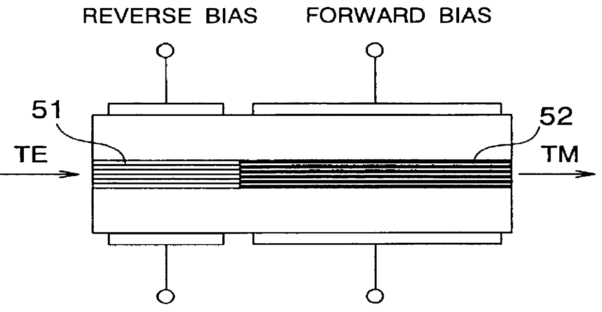
Referring to FIG. 2A, an exemplified semiconductor TE / TM mode converter according to the present invention comprises a semiconductor optical waveguide layer which is divided in the longitudinal direction thereof into two adjacent regions; a first region 11 and a second region 12 forming a combined resonator structure. The first region 11 has a compressive-strained MQW structure, whereas the second region 12 has a tensile-strained MQW structure. The first region 11 constitutes a saturable absorption region for TE mode light and the second region 12 constitutes an amplifying region for TM mode light in the combined resonator structure.

A diffraction grating 13 having a desired pitch is formed on the first region 11. The pitch of the diffraction grating 13 is such that the diffraction grating 13 has a higher ...


PUM

PropertyMeasurementUnit
incident wavelengthaaaaaaaaaa

Abstract

A semiconductor TE/TM mode converter comprises a semiconductor waveguide layer including a compressive-strained first region and a tensile-strained second region, and a diffraction grating formed on the first region. The first region and second region are reversed-biased and forward-biased, respectively. TE mode light incident on the facet of the first region generates TM mode light outgoing from the facet of the second region. The diffraction grating in the first region has selective reflectance against TM mode light and reflects the TM mode light toward the second region, to lower the lasing threshold of TM mode light and raise the conversion efficiency.

Description

(a) Field of the InventionThe present invention relates to polarization mode converter having a diffraction grating, for use in polarization mode conversion between TE mode light and TM mode light.(b) Description of the Related ArtAn optical waveguide-type polarization mode converter is known which is capable of being integrated with semiconductor lasers to form an optical semiconductor device. FIG. 1A is a schematic sectional view of an example of conventional TE / TM mode converters of this type. The TE / TM mode converter has a structure similar to that of a semiconductor laser of a combined resonator structure and is called as such.The TE / TM converter has a multiple quantum well (MQW) resonator structure wherein the resonator is divided in the longitudinal direction thereof into two regions 51 and 52. The first region 51 has a compressive-strained MQW structure wherein the compressive strain is introduced in the quantum well active layer, whereas the second region 52 has a tensile-s...

Claims


Application Information

Patent Timeline
Patent Type & Authority Patents(United States)
IPC IPC(8): G02F1/01G02F1/025G02B6/34G02F1/35G02F1/365G02B6/14H01S5/50H01S3/06H01S3/063H01S5/00H01S5/026H01S5/062H01S5/12
CPCB82Y20/00G02F1/01708H01S5/0265H01S5/5036G02F1/0353G02F2201/16H01S5/06236H01S5/12
Inventor DONG, HUANG YI
Owner NEC CORP
Why Eureka
Try Eureka