Stator produced by injection molding

a technology of hydrodynamic torque converter and stator blade, which is applied in the direction of gearing, liquid fuel engines,foundry moulding apparatus, etc., can solve the problems of over-extended 4-mm width required, unwanted attachments or accretions at stator blades, and expected breaking of chisels

Inactive Publication Date: 2000-09-26
ZF FRIEDRICHSHAFEN AG
View PDF13 Cites 13 Cited by
  • Summary
  • Abstract
  • Description
  • Claims
  • Application Information

AI Technical Summary

Problems solved by technology

Disadvantageously however the low viscosity or fluidity of the aluminum material in the heated state allows material to exit from a contacting zone between the two dies, resulting in unwanted attachments or accretions to form at the stator blades.
When cutting off the accretions, forces act on the inserted chisel which lead to expected breaking of the chisel, especially if the cutting edge of the chisel is very narrow in the circumferential direction.
But, as a detrimental consequence of this, there is formed an offset in the circumferential direction between the flow outlet of the stator blade and the flow inlet of the next guide wheel blade, such that the offset exceeds the 4-mm width required for the chisel.
As a result, the guide length of the stator blade for the flow passing through it is shortened, which leads to poorer efficiency and poorer characteristics, adversely reducing torque multiplication of the converter.
While this produces a stator having a smooth surface, the surface cannot be subjected to subsequent cutting machining

Method used


Image

  • Stator produced by injection molding
  • Stator produced by injection molding
  • Stator produced by injection molding

Examples


Embodiment Construction

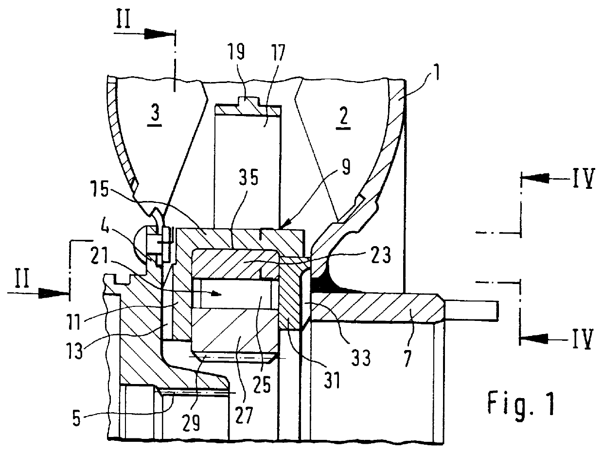
FIG. 1 shows in detail only that region of a hydrodynamic torque converter relating to the present invention. An illustration and description of the torque converter in its entirety has been omitted because torque converters of this kind are known from the prior art for example, from German reference DE 41 21 586 A1.

A pump shell 1 forms a pump wheel 2 that cooperates with a turbine wheel 3. A turbine hub 4 is fixedly connected in the radial inner region of the turbine wheel 3. A toothing 5 is arranged on the turbine hub 4 so as to engage a drive shaft, not shown, such as a transmission input shaft.

The pump shell 1 is fastened in the radial inner region to a hollow shaft 7 extending in the direction of a power take-off, as for example, an engine output shaft. A stator 9 is arranged axially between the pump wheel 2 and the turbine wheel 3. A first axial bearing 11 supports the stator 9 in the region between the turbine hub 4 and a freewheel 21 and a second axial bearing 31 supports th...


PUM

PropertyMeasurementUnit
Widthaaaaaaaaaa
Widthaaaaaaaaaa
Circumferenceaaaaaaaaaa

Abstract

A stator for a hydrodynamic torque converter which is produced by injection molding with axially drawn dies. The stator hub has stator blades produced by use of a thermoplastic material to fill the dies in the injection molding process. The stator blades are positioned relative to one another on the stator hub in such a way that the flow outlet of every stator blade is arranged at an offset of only the width of a gap relative to the flow inlet of the subsequent stator blade in the circumferential direction.

Description

1. Field of the InventionThe invention is directed to a stator for a hydrodynamic torque converter, and in particular a stator produced by an injection molding process using axially drawn dies. The stator has a hub having blades provided thereon.2. Description of the Relation ArtGerman reference DE 195 33 151 A1 discloses a stator for a hydrodynamic torque converter, the stator being arranged axially between a pump wheel and a turbine wheel. The stator carries stator blades by means of which hydraulic fluid flowing from the turbine wheel can be directed to the pump wheel at a desired angle.A stator of the type mentioned above can be produced in various ways. For reasons of economy, an injection molding process with axially drawn tools or dies is preferred, wherein the dies have fill spaces in which material is introduced by means of the injection molding process. After the material solidifies, the dies are drawn apart axially and, in so doing, release the guide wheel. Aluminum is us...

Claims


Application Information

Patent Timeline
IPC IPC(8): B29C45/26F16H41/00F16H41/28F16H41/24B29C45/14B29K101/12
CPCB29C45/2628F16H41/28B29L2031/087F16H2041/246F16H2041/285Y10S425/058
Inventor SASSE, CHRISTOPHDEHRMANN, UWE
Owner ZF FRIEDRICHSHAFEN AG
Why Eureka
Try Eureka