Processing device for crushing, conveying and plastifying thermoplastic synthetic material

a technology of thermoplastic synthetic material and processing device, which is applied in the direction of application, grain husking, grain treatment, etc., can solve the problems of poor thermal efficiency, high construction cost, and large space occupation, and achieve high torque at the processing drum, improve the charging effect of the extruder, and improve the effect of tamping

Inactive Publication Date: 2000-10-03
MANFRED DOBERSBERGER +1
View PDF10 Cites 29 Cited by
  • Summary
  • Abstract
  • Description
  • Claims
  • Application Information

AI Technical Summary

Benefits of technology

Even larger plastic parts are captured within the application of circulating knives, wherein two rows with in each case two knives in each row disposed oppositely to each other on the processing drum, which knives are disposed above the exit opening of the conveyor tube and wherein usually the extension can be found, which extension comminutes together with the fixed disposed knives the material, and the larger plastic parts are for such time and effectively comminuted by the combing running together with the fixedly disposed knives, until the larger plastic parts are captured by the extruder worm and are pulled in. In particular high peaks of torque at the processing drum are avoided thereby, if the knives are disposed st

Problems solved by technology

On the other hand, a disadvantage of this configuration is its poor thermal efficiency, since the comminuting energy, which is transferred in the grinder in the form of frictional heat onto the plastic material, is again discharged to the surroundings based on the subsequent intermediate storage in the storage silo and thus is lost for the extrusion process.
In addition this configuration has the disadvantage, that it requires a considerable amount of space and its construction is very costly.
However, very substantial disadvantages exist, because this arrangement can only be fed with material particles of limited size and the feeding always has to be performed uniformly, since otherwise the drive motor can be overloaded or the plastic material still in the container can melt down, which may cause clogging or may cause the cutter disk to jam.
However, this necessitates a process of separating the comminuted material according to the size of each piece, which proves to be expensive and complicated, in particular in the case of pressed plastic material or in the case of large solid parts that have to b

Method used


Image

  • Processing device for crushing, conveying and plastifying thermoplastic synthetic material
  • Processing device for crushing, conveying and plastifying thermoplastic synthetic material
  • Processing device for crushing, conveying and plastifying thermoplastic synthetic material

Examples


Embodiment Construction

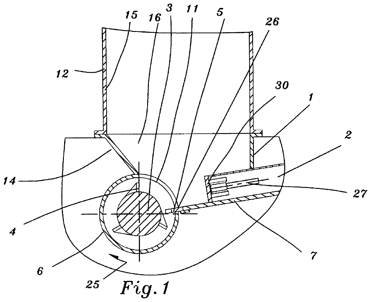
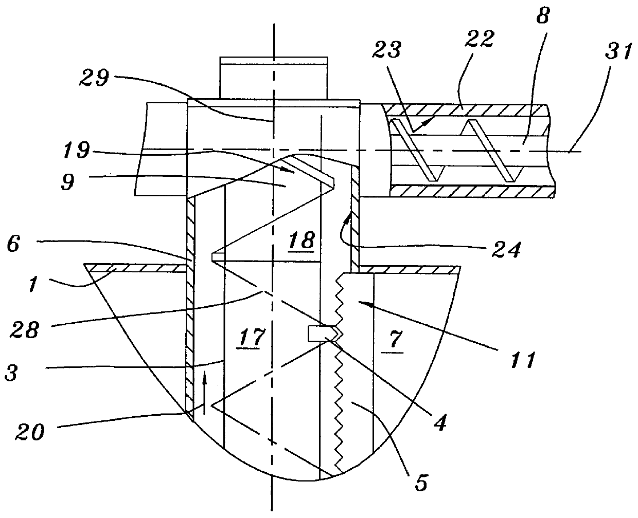
There is shown in FIG. 1 an apparatus comprising a machine casing 1 with a feed funnel 12 placed thereon, wherein the lower connecting feed shaft 14 of the feed funnel 12 is closed with a floor plate 7, wherein the floor plate 7 runs downwardly inclined and wherein the floor plate 7 ends at the feed opening 11 of a horizontally aligned conveyor tube 6 of the comminuting apparatus.

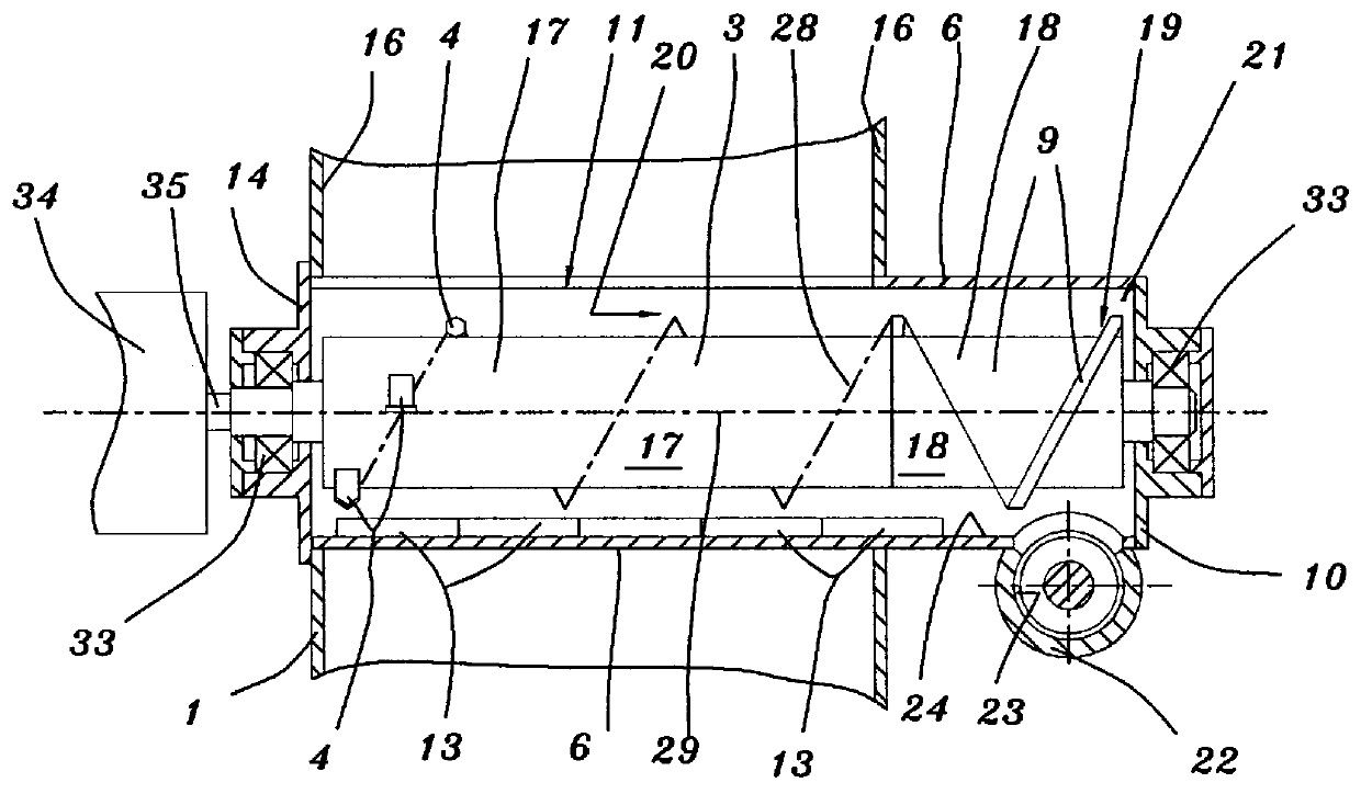
A processing drum 3 is disposed in a horizontal position in the conveyor tube 6, is rotatably inserted, and the processing drum 3 is on two sides supported at bearings 33 (FIG. 2) and is drivable by drive shaft 35 connected to a motor 34.

The processing drum 3 comprises a part 17 carrying the knives, wherein the knives 4 are attached radially protruding along a circumferential screw line 28 of the knife carrying part 17 and out of a part 18 carrying the discharge member following to the knife supporting part 17, wherein the discharge members 19 of the discharge support carrying part 18 are formed by a convey...


PUM

PropertyMeasurementUnit
Diameteraaaaaaaaaa
Lengthaaaaaaaaaa
Temperatureaaaaaaaaaa

Abstract

A unit for processing thermoplastic synthetic material comprising a machine housing (1) with a delivery cone (12) in whose feed shaft (14) a driven slider (30) presses synthetic material which is to be processed and which is located on a base plate (7) through a feed inlet (11) of a conveyor tube (6) against a processing drum (3) which is placed perpendicularly in the conveyor tube (6) in relation to the direction of the movement of the slider (30). The slider (30) extends over the entire length of the feed inlet (11) which itself extends over the entire blade supporting section (17) of the processing drum (3). Blades (4) are placed thereon in a helical line and operate in conjunction with a fixed counter blade (5) which is fastened to the opening edge (25) of the feed inlet (11). The blades (4) and the associated screw conveyor (9) convey disintegrated synthetic material in axial direction (20) though the conveyor tube (6) towards an outlet (10), which leads downwards into the screw tube (22) of the extruder screw (8) through which the synthetic material is delivered.

Description

1. Field of the InventionThe present invention relates to a processing device for comminuting, conveying and plasticizing of thermoplastic synthetic material comprising a conveying device, a comminuting device and a screw-type extrusion machine.2. Brief Description of the Background of the Present Invention Including Prior ArtIt is known to comminute plastic material in a grinder and to transport the plastic material into a silo, from which silo the pre-comminuted plastic material is then fed through a tamping device to an extruder, the latter being in most cases a screw-type extrusion machine. This configuration has the advantage that the silo offers a storage capacity by way of which fluctuations in the production of material can be balanced.On the other hand, a disadvantage of this configuration is its poor thermal efficiency, since the comminuting energy, which is transferred in the grinder in the form of frictional heat onto the plastic material, is again discharged to the surr...

Claims


Application Information

Patent Timeline
IPC IPC(8): B02C18/14B02C18/22B02C18/06B29B17/00B29B17/04
CPCB02C18/145B02C18/148B29B17/04B29B17/0026B02C18/2233B02C2018/188Y02W30/62
Inventor BARTH, GEROLDDOBERSBERGER, MANFREDFELLINGER, MARKUSKROISS, GUNTER
Owner MANFRED DOBERSBERGER
Why Eureka
Try Eureka