Production of color filter by forming light-screening layer and irradiating resin layer to achieve ink-accepting property

a color filter and resin technology, applied in photomechanical treatment, instruments, optics, etc., can solve the problems of inability to meet the requirements of all required properties, production cost is necessarily increased, yield reduction, etc., to achieve shorten production steps, high reliability, and low cost

Inactive Publication Date: 2000-10-03
CANON KK
View PDF39 Cites 27 Cited by
  • Summary
  • Abstract
  • Description
  • Claims
  • Application Information

AI Technical Summary

Benefits of technology

It is therefore an object of the present invention to provide a production process of a color filter substrate, which satisfies necessary properties such as heat resistance, solvent resistance and resolution, and permits the shortening of production steps to produce the color filter substrate at a low cost, and a color filter substrate with high reliability produced by this process, and particularly to provide a production process of a color filter substrate, which satisfies ink-jet recordability upon formation of a color filter by an ink-jet printing system and permits the provision of a color filter substrate with high reliability in that color mixing and color irregularity are prevented upon application of inks, and a liquid crystal display device excellent in color display characteristics using such a color filter substrate at a low cost.

Problems solved by technology

However, no process satisfying all the required properties is yet established under the circumstances.
Therefore, the production cost is necessarily increased.
There is also offered a problem that a yield is reduced as the number of processes increases.
Besides, in the electrodeposition process, formable patterns are limited.
It is hence difficult to apply this process to a TFT color liquid crystal display device in the existing technique.
Further, the printing process involves a drawback that resolution is poor, and is hence unfit to form fine-pitch patterns.
However, these processes using the ink-jet system are yet insufficient.
In particular, the following problems arise upon the production of a color filter according to the ink-jet printing system.
(2) Blank areas occurred at boundaries between colored portions and black matrices, and color irregularity caused by the distribution of optical density in colored pixels.
However, this method requires two coating steps, since the pattern of the silicone rubber is formed on a photosensitive resin layer, and the silicone rubber layer or the silicone rubber layer and the photosensitive resin layer are then removed by photolithography, and is hence disadvantageous from the viewpoint of production process.
(1) the fine silicone particles are left as a residue after development and transferred to the member for forming black matrices, and so defects are caused in the resulting black matrices; and
(2) since the resolution of the photosensitive resin is deteriorated if the amount of the fine-silicone particles added is increased, this process is unfit to form fine-pitch patterns.
However, this process
involves a problem that since even edge parts of the black matrices formed with the photosensitive resin are covered with the photosensitive silicone, blank areas occur at boundaries between the colored portions (pixels) and the black matrices.

Method used


Image

  • Production of color filter by forming light-screening layer and irradiating resin layer to achieve ink-accepting property
  • Production of color filter by forming light-screening layer and irradiating resin layer to achieve ink-accepting property
  • Production of color filter by forming light-screening layer and irradiating resin layer to achieve ink-accepting property

Examples


example 1

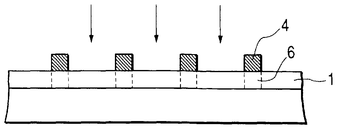
Poly(phenylmethyl)silane was applied by spin coating onto a glass base, so as to give a coating thickness of 1.2 .mu.m, and prebaked at 90.degree. C. for 20 minutes. A resist for black matrices (V-259, trade name, product of Nippon Steel Chemical Co., Ltd.) was formed so as to give a film thickness of 1.5 .mu.m, and subjected to predetermined exposure, development and heat treatments, thereby forming black matrices having a predetermined pattern on the poly(phenylmethyl)silane layer.

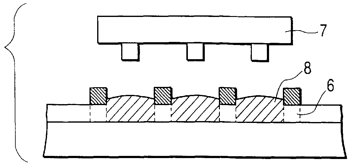
After the poly(phenylmethyl)silane layer was subjected to whole-surface exposure from the side of the black matrices in an exposure value of 3 J / cm.sup.2, an ink-jet printing apparatus was used to color the exposed areas of the poly(phenylmethyl)silane layer on a matrix pattern of R, G and B with color inks having the following respective compositions:

______________________________________ R (Red) ink: Water 58 parts Diethylene glycol 25 parts

Methyl alcohol 10 parts R dye (C.I. Direct Red 80) 4 parts Met...

example 2

A color filter substrate was produced in the same manner as in Example 1 except that a condensation reaction product of 1,4-bis(chlorosilyl)benzene was used as the resin composition for coloration. The color filter substrate was observed through an optical microscope. As a result, defects such as color mixing, blank areas and color irregularity in pixels were not observed.

example 3

A color filter substrate was produced in the same manner as in Example 1 except that a polysilane synthesized from phenylmethyldichlorosilane and methyltrichlorosilane was used as the resin composition for coloration, and color inks having the following respective compositions were used as the color inks.

______________________________________ R (Red) ink: Water 61 parts Diethylene glycol 25 parts Methyl alcohol 10 parts R dye (the same dye as in Example 1) 4 parts. G (Green) ink: Water 60 parts Diethylene glycol 25 parts Methyl alcohol 10 parts G dye (the same dye as in Example 1) 5 parts. B (Blue) ink: Water 61 parts Diethylene glycol 25 parts Methyl alcohol 10 parts B dye (the same dye as in Example 1) 4 parts. ______________________________________

The color filter substrate produced in this example was observed through an optical microscope. As a result, defects such as color mixing, blank areas and color irregularity in pixels were not observed.


PUM

PropertyMeasurementUnit
thicknessaaaaaaaaaa
thicknessaaaaaaaaaa
thicknessaaaaaaaaaa

Abstract

Disclosed herein is a process for producing a color filter substrate, which comprises the steps of forming a resin layer for coloration, which develops an ink-accepting property by irradiation of light, on a base; forming a light-screening layer on the resin layer for coloration; exposing the resin layer for coloration through the light-screening layer as a mask; and applying color inks to the resin layer for coloration.

Description

BACKGROUND OF THE INVENTION1. Field of the InventionThe present invention relates to a process for the preparation of a color filter substrate suitable for use in color liquid crystal display devices.2. Related Background ArtWith the advancement of personal computers, particularly, portable personal computers in recent years, the demand for liquid crystal display devices, particularly, color liquid crystal display devices tends to increase. It is however necessary to reduce the cost of the color liquid crystal display devices for further spreading them. There is an increasing demand for reduction in the cost of color filters particularly given much weight from the viewpoint of the cost.Various processes have heretofore been attempted for meeting the above demand while satisfying properties required of the color filters. However, no process satisfying all the required properties is yet established under the circumstances. The typical production processes of color filters will hereina...

Claims


Application Information

Patent Timeline
Patent Type & Authority Patents(United States)
IPC IPC(8): G02B5/20G02F1/1335
CPCG02B5/201
Inventor SHIBA, SHOJITAKAO, HIDEAKIYOKOYAMA, RYUICHIKASHIWAZAKI, AKIOSOBUE, MASASHIOKADA, TAKESHI
Owner CANON KK
Why Eureka
Try Eureka