Optical fiber secured with a photosetting resin covered with a UV light-transmissive plate

a technology of photosetting resin and optical fiber, which is applied in the direction of optics, optical elements, instruments, etc., can solve the problems of increasing the cost of the optical semiconductor device, the jacket is not thermally resistant, and the structure and respective working steps are not easy to simplify, so as to reduce the number of assembling steps and prevent cracking in the photosetting resin. , the effect of high reliability

Inactive Publication Date: 2000-10-10
RENESAS ELECTRONICS CORP
View PDF2 Cites 31 Cited by
  • Summary
  • Abstract
  • Description
  • Claims
  • Application Information

AI Technical Summary

Benefits of technology

The present invention has been made in view of the situations of the prior art described above, and has as its object to provide a highly reliable optical semiconductor device in which the number of assembling steps is reduced, the fixing strength of the bare fiber of an optical fiber with a photosetting resin is increased, cracking in the photosetting resin is prevented, and the stress on the bare fiber can be moderated.

Problems solved by technology

The jacket is not thermally resistant.
This structure has a large number of components constituting the optical semiconductor device and a large number of assembling steps, leading to an increase in cost of the optical semiconductor device.
However, this structure requires the optical fiber support member that must be machined specially, and the bare fiber of the optical fiber must be inserted in a small hole formed in the optical fiber support member, still leaving a problem in simplifying the structure and the respective working steps in assembly.
When this optical semiconductor device was manufactured on a trial base by using an ultraviolet curing resin as the photosetting resin and was subjected to performance evaluation, the following problems arose.
Then, sufficient curing cannot be performed, and the fixing strength of the bare fiber tends to be insufficient.
In particular, the ultraviolet curing resin in the notch or groove where the bare fiber is inserted cannot be sufficiently cured.
When this ultraviolet curing resin is cured, cracking occurs in the resin to decrease the fixing strength.
In this case, in order to prevent this, silica was filled in the ultraviolet curing resin, and the amount of silica as a filler was changed, so that the coefficient of thermal expansion of the ultraviolet curing resin at a glass transition temperature or less was decreased from 7.7E-5 / .degree. C. to 1.0E-5 / .degree. C. However, it was difficult to improve the fixing strength.
When the coefficient of thermal expansion was decreased to less than 1.5E-5 / .degree. C., the viscosity of the ultraviolet curing resin increased sharply to impair the filling performance.
It was confirmed that a through hole was formed due to filling failure, thus impairing the reliability in airtightness.
Since the bare fiber is completely covered with the ultraviolet curing resin and fixed, it is damaged by a stress applied to the case or optical fiber.

Method used


Image

  • Optical fiber secured with a photosetting resin covered with a UV light-transmissive plate
  • Optical fiber secured with a photosetting resin covered with a UV light-transmissive plate
  • Optical fiber secured with a photosetting resin covered with a UV light-transmissive plate

Examples


Embodiment Construction

The several preferred embodiments of the present invention will be described in detail with reference to the accompanying drawings.

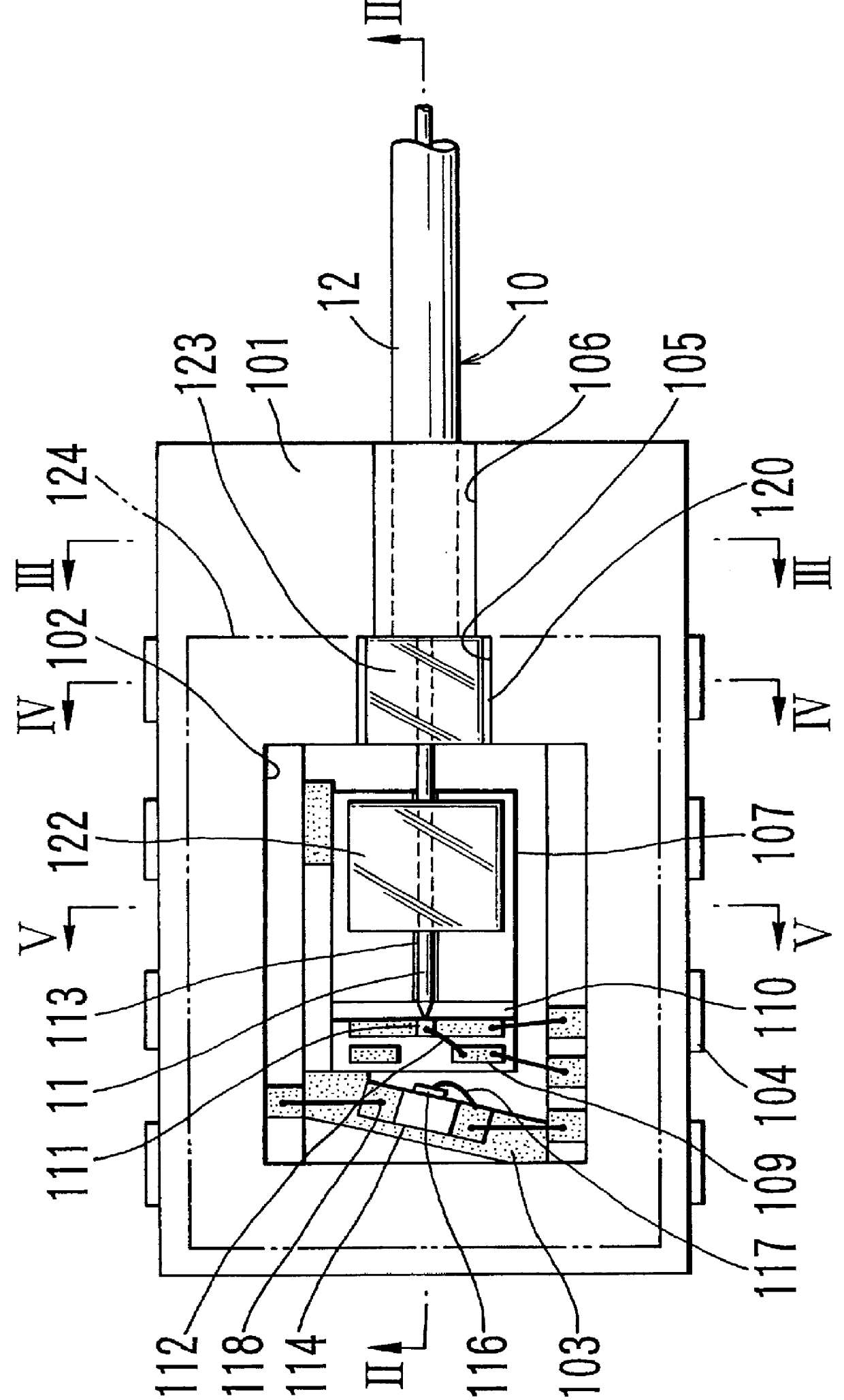
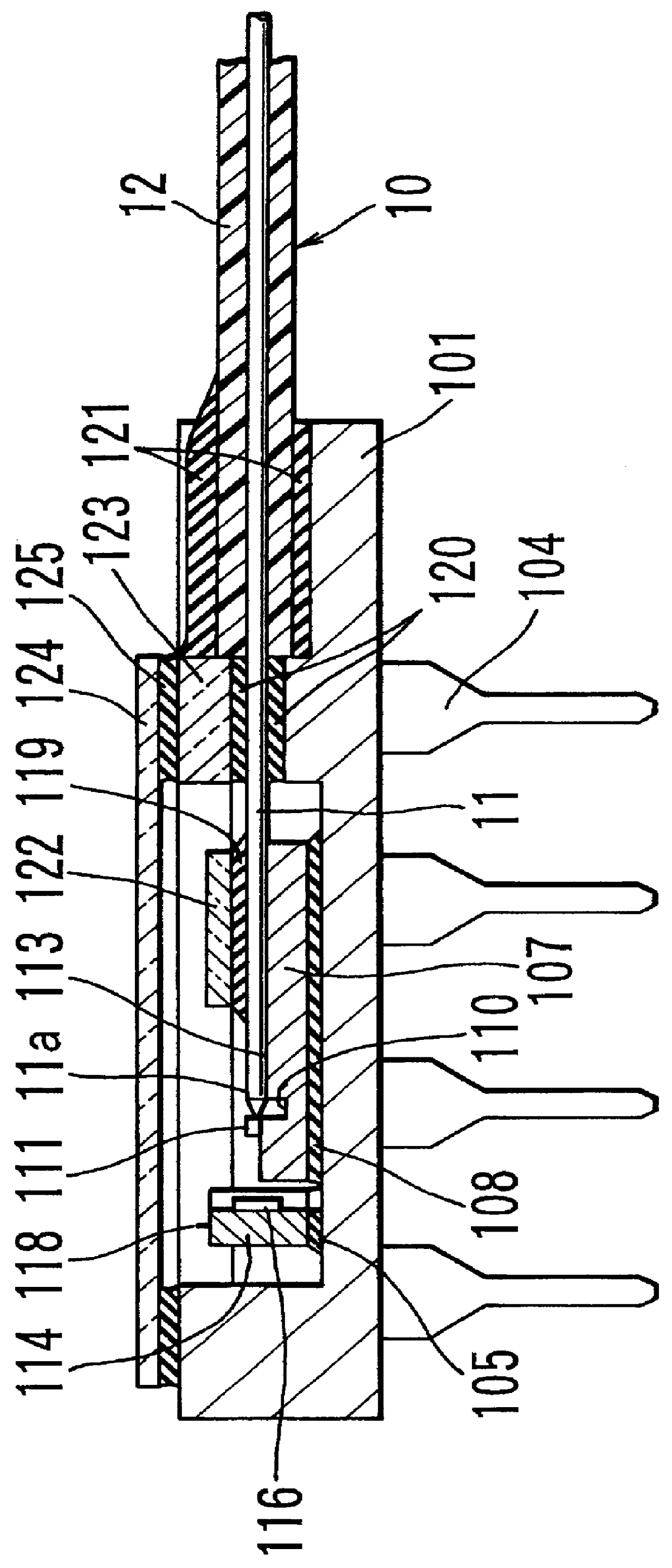
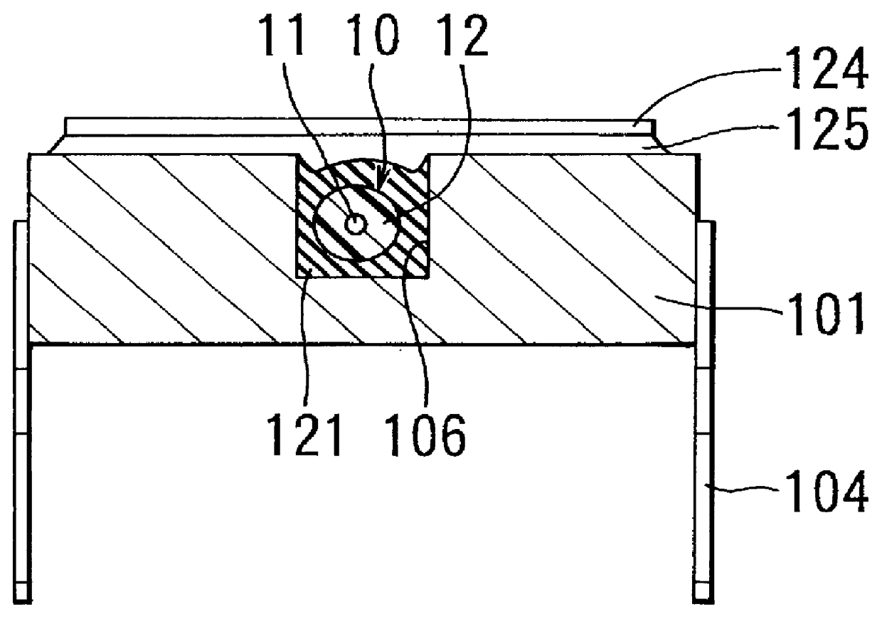
FIG. 1 is a plan view of the first embodiment of the present invention, and FIGS. 2 to 5 are sectional views taken along the lines II--II, III--III, IV--IV, and V--V, respectively, of FIG. 1. FIG. 6 is a schematic perspective view showing the main portion in an exploded state. Referring to FIGS. 1 to 6, an optical fiber 10 is constituted by a bare fiber 11 made of glass or the like, and a jacket 12 made of a polyethylene resin or the like to cover the bare fiber 11. A case 101, to which one end portion of the optical fiber 10 is connected and supported, has a rectangular shape and is made of a ceramic material, e.g., alumina or aluminum nitride. A rectangular cavity 102 is formed in a region of the upper surface of the case 101 close to one end in the longitudinal direction. A necessary metallized pattern 103 is formed on the inner bottom surface of the ...


PUM


Abstract

An optical semiconductor device, having an optical element mounted in a case and an optical fiber fixed to the case with a first photosetting resin, includes a transparent plate placed on a surface layer portion of the first photosetting resin to transmit light that cures the first photosetting resin. The transparent plate is integrated with the cured photosetting resin, and the optical element is a light emitting element.

Description

BACKGROUND OF THE INVENTIONField of the InventionThe present invention relates to an optical semiconductor device having an optical element such as a light emitting element or light receiving element, and an optical transmission optical fiber optically coupled to the optical element and, more particularly, to a mounting structure for the optical fiber.DESCRIPTION OF THE PRIOR ARTIn an optical semiconductor device of this type, an optical element is mounted in a case. An optical fiber is axially aligned with the optical element and fixed to the case. After that, the optical coupling region of the optical element and optical fiber is airtightly sealed. In the optical fiber, a bare fiber made of glass is covered with a polyethylene jacket. The jacket is not thermally resistant. If the jacket portion is fixed to the case, the fixed state is degraded by heat, and the axial position of the jacket shifts with respect to the optical element. To prevent this, a structure in which the jacket ...

Claims


Application Information

Patent Timeline
Patent Type & Authority Patents(United States)
IPC IPC(8): G02B6/42
CPCG02B6/4239G02B6/4248G02B6/4246G02B6/4286G02B6/4259G02B6/4243G02B6/4265G02B6/4269
Inventor HASHIZUME, SHOZIHASEGAWA, YOSHIHIROUEDA, HIRONORI
Owner RENESAS ELECTRONICS CORP
Why Eureka
Try Eureka