Add/drop multiplexer node

a multiplexer and node technology, applied in multiplex communication, electromagnetic repeaters, instruments, etc., can solve the problems of high spontaneous emission of optical amplifiers that are required in each node, no optically complete nodes, and serious problems

Inactive Publication Date: 2000-10-17
TELEFON AB LM ERICSSON (PUBL)
View PDF6 Cites 58 Cited by
  • Summary
  • Abstract
  • Description
  • Claims
  • Application Information

AI Technical Summary

Benefits of technology

One advantage of the invention is that any of a number of existing channels can be chosen to be dropped to and added from a line terminal at a node. Because of this channels can be rerouted because of traffic variations. Another advantage of the invention is that the noise level in the node because of amplifier spontaneous emission and crosstalk is substantially lowered, especially when the invention is used in a ring configured network. Another advantage is that the problem of polarization mode dispersion is alleviated, so that channels added to a network at one node can be dropped at another node that is placed more than three nodes away from said one node.

Problems solved by technology

However, none of the existing nodes are completely optical, but have all, in case optical signal transmission lines are used, electrical / optical and optical / electrical interfaces.
These devices do however have a few limitations.
If several channels are to be dropped, multiplexers and demultiplexers as well as several such SONET ADMs have to be added to the node, which is a complicated way of performing selective adding and dropping of a predetermined number of channels.
Another problem with such nodes is that if several nodes are coupled together in cascade, the spontaneous emission from optical amplifiers that are required in each node tends to get high and become a serious problem.
One drawback is that the filtering function is not very selective so that about half the input power is filtered away.
Another problem with this arrangement is that it has a relatively high level of crosstalk.
Yet another problem is the polarization mode dispersion effect, which imposes a restraint on a network using this arrangement.

Method used


Image

  • Add/drop multiplexer node
  • Add/drop multiplexer node
  • Add/drop multiplexer node

Examples


Embodiment Construction

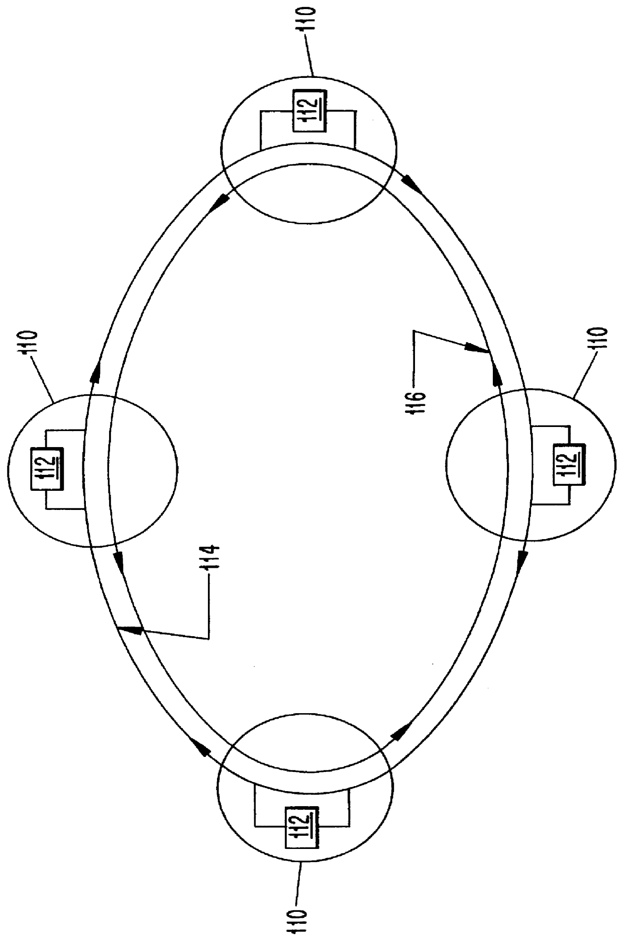
A preferred embodiment of the present invention will now be described in detail. FIG. 1 shows a schematic diagram of a ring shaped optical network according to the invention. The present invention is however not limited to this type of network configuration, but can just as well be used in a bus shaped or mesh shaped network as well as in other types of networks. The network in FIG. 1 is termed a self-healing ring network. The network according to FIG. 1 consists of four nodes 110, which all are add / drop multiplexer nodes according to the invention. Two circular optical fibers 114 and 116 run through each node 110. These fibers are shown in the form of a first ring 114 encircling a second ring 116. A line terminal 112 in each node 110 has two connections with the first ring 114, one for adding and the other for dropping traffic. The first ring 114 is termed a working outer ring. The second ring 116 is termed a protection inner ring. In parts of the fibers, between the nodes, amplifi...


PUM


Abstract

PCT No. PCT / SE96 / 00813 Sec. 371 Date Feb. 10, 1998 Sec. 102(e) Date Feb. 10, 1998 PCT Filed Jun. 20, 1996 PCT Pub. No. WO97 / 01897 PCT Pub. Date Jan. 16, 1997An add / drop multiplexer node in an optical network comprises an optical channel-selective switch. The switch is operable in bar and cross states and has a first input for the reception of optical multiplexed channels, a second input connected to an output on a line terminal associated with the node for adding channels, a first output, which is bar coupled to the first input and connected to a line terminal input for dropping channels and a second output, which is bar coupled to the second input. A predetermined number of channels to be dropped are selected and the channel-selective switch cross-couples non-selected channels from the first input to the second output.

Description

This application is a 371 of PCT / SE96 / 00813 filed Jun. 20, 1996.The present invention relates to a method of adding and dropping optical channels to and from a line terminal that is connected to an optical add / drop multiplexer node, an optical add / drop multiplexer node as well as to an optical network comprising at least one such optical add / drop multiplexer node.STATE OF THE ARTThere exist within the art nodes for the selective adding and dropping of a predetermined number of multiplexed channels from and to a line terminal, which is associated with the node. However, none of the existing nodes are completely optical, but have all, in case optical signal transmission lines are used, electrical / optical and optical / electrical interfaces. The adding and dropping of channels in these nodes takes place in the electrical part of the node. This naturally imposes a restraint on the speed with which signals can be transferred in such a system and on the compatibility of different transmissi...

Claims


Application Information

Patent Timeline
Patent Type & Authority Patents(United States)
IPC IPC(8): H04J14/02H04B10/213H04Q11/00H04B10/29H04J14/00H04B10/035H04B10/079H04B10/2507H04B10/27H04B10/275H04B10/296H04J3/08H04Q3/52
CPCH04J14/0212H04J14/0213H04J14/0221H04J14/0291H04Q11/0062H04J14/0283H04Q2011/0092H04Q2011/0013H04Q2011/0043H04Q2011/0049H04Q2011/0081H04Q2011/0083H04Q11/0071
Inventor ANDREOZZI, PAOLOMERLI, STEFANONORBIATO, RENATOTESTA, FRANCESCO
Owner TELEFON AB LM ERICSSON (PUBL)
Why Eureka
Try Eureka