Optical localization fiber

a localization fiber and optical fiber technology, applied in the field of optical localization fibers, can solve the problems of inability to easily ascertain the precise depth of the hookwire, inability to fluoroscopic guidance, and inability to precisely place the hookwire tip

Inactive Publication Date: 2000-10-24
HUSSMAN KARL L
View PDF1 Cites 68 Cited by
  • Summary
  • Abstract
  • Description
  • Claims
  • Application Information

AI Technical Summary

Benefits of technology

The present invention is directed to an optical localization fiber with a hooked tip for preoperative localization of breast lesions identified by x-ray mammography, ultrasound, MRI, or nucle

Problems solved by technology

This maneuver may displace the hookwire tip however.
In addition, unless the fluoroscopic tube can be angled to yield mediolateral and anteroposterior projections, the precise depth of the hookwire cannot be readily ascertained.
For these reasons, fluoroscopic guidance is not feasible.
Both the hookwire and carbon trail methods are cumbersome in actual use.
The tip of a hookwire cannot be see

Method used


Image

  • Optical localization fiber
  • Optical localization fiber
  • Optical localization fiber

Examples


Embodiment Construction

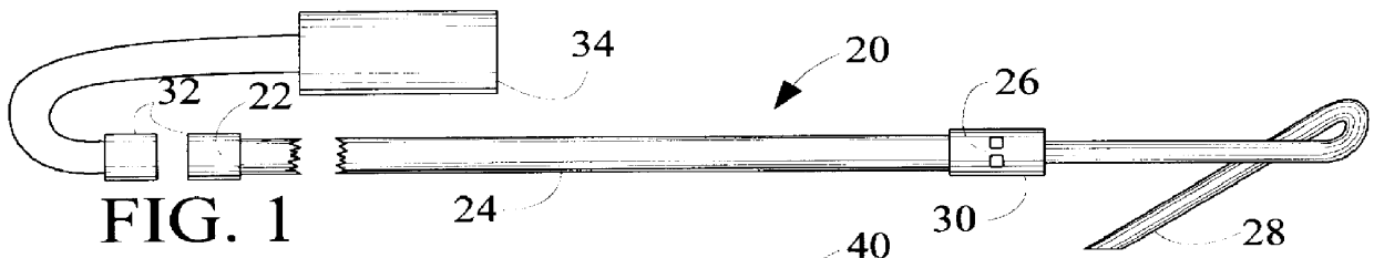
FIG. 1 illustrates a side view of a diffusing optical localization fiber 20 in accordance with the present invention having an origin 22, a shaft 24, and an optical fiber tip 26. A metallic or plastic hook 28 is bound to the tip by means of a connection 30. The hook has a spring action to engage in tissue once the localization needle is withdrawn. A sectional view of a localization needle with an optical fiber inside prior to insertion is shown in FIG. 11. Radiant light emanating from the localization fiber tip may be diffused by the connector 30 if it is made of a translucent material including plastic quartz and ground glass. Alternatively, the connector 30 may be opaque, but fenestrated to allow light to emanate from the optical fiber tip 26. A coupler 32 is located at the origin 22 of the diffusing optical localization fiber 20 to unite with a laser or other light source 34.

FIG. 2 illustrates a longitudinal cross sectional view of an optical fiber 40 with cladding and / or coating...


PUM


Abstract

An optical localization fiber 20 is provided suitable for preoperative localization of soft tissue lesions by x-ray mammography, CT, MRI, ultrasonography, or nuclear medicine. A hook 28 is carried by the optical fiber for retaining the fiber in soft tissue. The tip 26 of the optical fiber is visible through the soft tissue when the proximal end of the optical fiber is attached to a light source 170. Other embodiments include clad or coated 42 optical fibers, bundled optical fibers 156, hooks which are metallic 82, braided 66, and multiple 128, and a helix 162.

Description

The present invention relates generally to preoperative tissue localization apparatus and more particularly to preoperative breast localization by x-ray radiography, CT ultrasonography, nuclear medicine or magnetic resonance imaging (MRI).The current state of the art of preoperative breast tumor localization requires the placement of either a metallic hookwire or a trail of medical grade powdered carbon suspension proximate to the tumor via a localization needle. In the former method, x-ray mammography, ultrasound, or magnetic resonance imaging is used to visualize the lesion in question. The breast is then fixed by compression means, non-compressive immobilization means, or, in the case of ultrasound, manually. A needle is inserted into the breast so that its tip lies proximate to the breast lesion. If carbon localization is used, a trail of carbon is formed from the lesion to the skin surface as the carbon suspension is injected through the needle as the needle is withdrawn. If ho...

Claims


Application Information

Patent Timeline
IPC IPC(8): A61B19/00A61B5/00A61B18/20A61B18/22
CPCA61B5/0084A61B5/0091A61B5/4312A61B19/54A61B5/6848A61B5/061A61B5/4887A61B2019/5445A61B2018/2261A61B2019/5206A61B2019/5408A61B90/39A61B2090/306A61B2090/3908A61B2090/3945
Inventor HUSSMAN, KARL L.
Owner HUSSMAN KARL L
Why Eureka
Try Eureka