Micromachined electrical field-flow fractionation system

a technology of microchannel devices and fractionation systems, applied in the direction of electrolysis, diaphragms, chemical vapor deposition coatings, etc., can solve the problems of low throughput, low resolution, and too slow, and achieve the effect of improving resolution

Inactive Publication Date: 2000-10-24
UTAH RES FOUND UNIV OF THE
View PDF18 Cites 133 Cited by
  • Summary
  • Abstract
  • Description
  • Claims
  • Application Information

AI Technical Summary

Benefits of technology

It is a primary object of the present invention to provide a microchannel device for an electrical field-flow fractionation system which can separate various species of molecules or particulates in solution with enhanced resolution.

Problems solved by technology

The majority of these methods, however, have various difficulties which include being too slow, too complicated, low in throughput, low in resolution, and too expensive to be practical for commercial and industrial applications.
Chemical separations are observed, however, to have the undesirable effect of denaturing proteins, and are therefore unsuitable for certain applications.
Centrifugation can be used to separate cells and organelles, although this technique often fails to resolve different types of cells due to similarities in cell densities.
Typical electrophoresis systems require very high field strengths, which can result in the unwanted formation of electrolysis by-products in the vicinity of the electrodes.
Conventional electrophoresis systems also employ a vertically oriented channel through which the sample containing the fluid must flow, which can result in the disadvantage of distortion in laminar flow conditions due to the effects of gravity.
The EFFF techniques have all of the advantages of electrophoretic separation systems, but in addition, can satisfactorily perform separation of cells, large molecules, colloids, emulsions, and delicate structures such as liposomes, which cannot be accomplished by conventional electrophoretic systems.
However, the plastics which have been hitherto implemented have been the source of complications in the fabrication steps.

Method used


Image

  • Micromachined electrical field-flow fractionation system
  • Micromachined electrical field-flow fractionation system
  • Micromachined electrical field-flow fractionation system

Examples


example 2

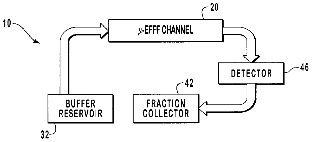
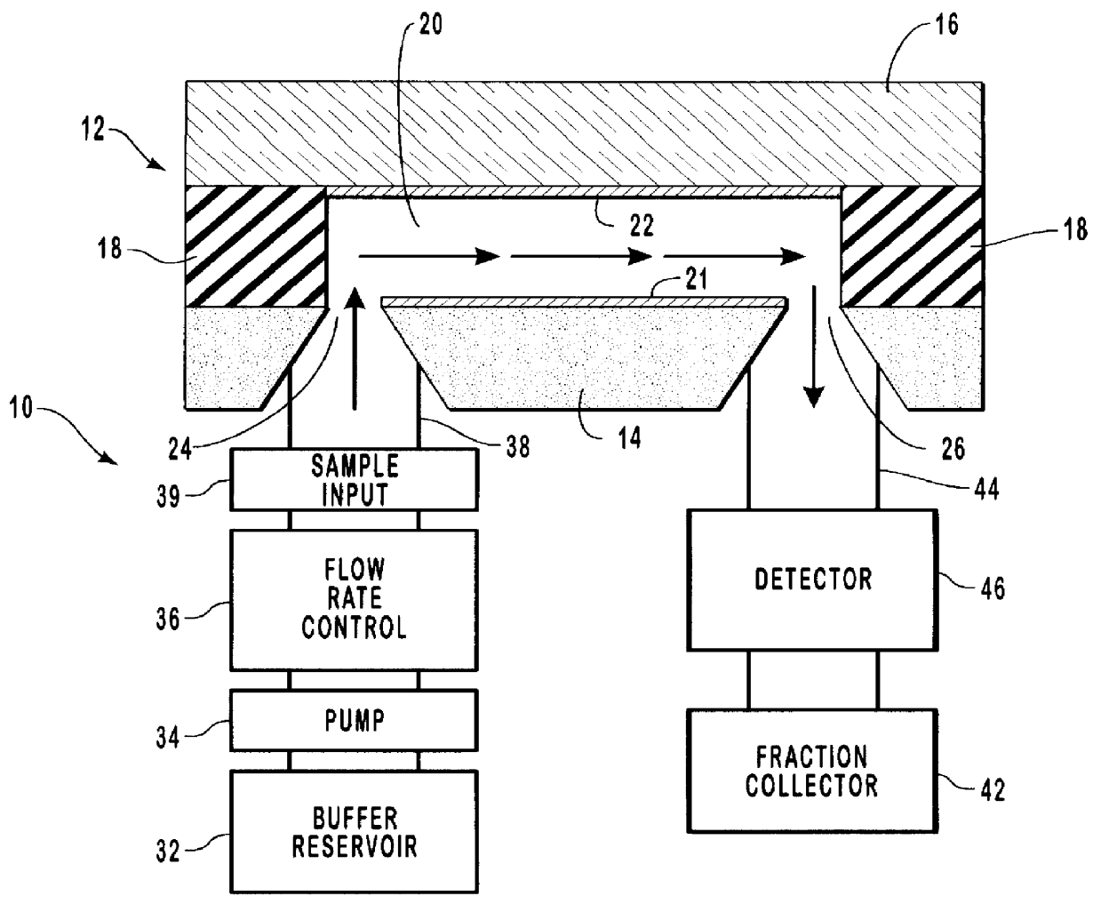
In order to perform separations using the microchannel devices fabricated according to the procedure described in Example 1, one entrance of a "T" connector is attached to the steel tubing on the silicon substrate. Another entrance of the T connector is covered with a septum for sample input. The sample is injected through the septum and into the T connector using a 10 .mu.L Hamilton syringe containing the sample plug. The other opening on the T connector is linked to a syringe pump using 10 cm of Teflon tubing with an outer diameter of 0.8 mm, and an inner diameter of 350 .mu.m. The output port is connected to a detector such as a Linear UV-106 absorbance detector (capable of monitoring extinction at 254 nm) by using 3 cm of 350 .mu.m inner diameter Teflon tubing. The fluid output from the detector can be connected to a fraction collector if desired. The detector is electrically connected to a recording device (e.g., a PC or strip chart recorder) which collects the data output from...

example 3

The microchannel devices fabricated according to the procedure described in Example 1 were tested for mechanical integrity of the microchannels by forcing fluids through the microchannels and checking for leaks. It was found that the microchannels can withstand fluid velocities as high as 4 cm / sec, while still maintaining mechanical integrity. Normal operating flows are typically about 1 cm / sec or lower.

example 4

A photosensitive polyimide material for use in the microchannel device of the invention was tested for potential swelling. The photosensitive polyimide material was spun on 6 silicon wafers at a series of thicknesses (estimated). The polyimide material was patterned in the same manner as for the .mu.-EFFF devices described in Example 1, and was cured for 24 hours at 285.degree. C. The cured polyimide was then soaked in deionized water for 24 hours at room temperature. The results of this test are shown in Table 1 below.

Examination of Table 1 reveals that polyimide swelling in water is potentially significant. Since the channel thickness or height is of critical importance in .mu.-EFFF systems, a variation in channel thickness can have a ripple effect through the system and cause results that vary from the expected. Nevertheless, the 2.2% average swelling is small enough not to cause significant differences, especially when considering that the amount of swelling in the actual device...


PUM

PropertyMeasurementUnit
lengthaaaaaaaaaa
lengthaaaaaaaaaa
lengthaaaaaaaaaa

Abstract

A micromachined system for electrical field-flow fractionation of small test fluid samples is provided. The system includes a microchannel device comprising a first substrate having a planar inner surface with an electrode formed thereon. A second substrate having a planar inner surface with an electrode formed thereon is positioned over the first substrate so that the respective electrodes face each other. An insulating intermediate layer is interposed between the first and second substrates. The intermediate layer is patterned to form opposing sidewalls of at least one microchannel, with the electrodes on the substrates defining opposing continuous boundaries along the length of the microchannel. Inlet and outlet ports are formed in one or both substrates for allowing fluid flow into and out of the microchannel. The microchannel device can be fabricated with single or multiple microchannels therein for processing single or multiple test fluids. During operation, a voltage differential is applied to the electrodes in order to induce an electric field across the microchannel. This separates particles of different types present in a fluid injected into the microchannel. The separated particles in the fluid can be collected or further processed as desired.

Description

1. The Field of the InventionThe present invention relates to a system and method for the separation of biological and chemical materials which are in a liquid solution. More particularly, the present invention relates to a micromachined system for separation of molecules and particulate materials which utilizes electrical field-flow fractionation techniques.2. The Relevant TechnologyField flow fractionation techniques are commonly used to perform separation and analysis of molecules and large molecular complexes which are in solution form. In theory, several different mechanisms can be employed to separate particles of differing varieties from a fluid stream; an example being separation by differences in mass or electrochemical potential through the application of an appropriate "driving" force. This driving force can be used to induce a displacement of a particular species in a certain direction such as towards what is commonly termed the "accumulation wall." From a practical poin...

Claims


Application Information

Patent Timeline
Patent Type & Authority Patents(United States)
IPC IPC(8): B03C5/02B03C5/00B81B1/00B81C1/00G01N30/00
CPCB03C5/026B81B1/00B81C1/00357G01N30/0005B81C2201/019G01N2030/0035G01N30/466G01N30/6095
Inventor FRAZIER, A. BRUNOCALDWELL, KARIN D.GALE, BRUCE K.
Owner UTAH RES FOUND UNIV OF THE
Why Eureka
Try Eureka