Wafer level burn-in and test thermal chuck and method

a technology of thermal chuck and burn-in, which is applied in the direction of hot plate heating arrangement, semiconductor/solid-state device testing/measurement, instruments, etc., can solve the problem that the object designed with mechanical constraints will (in all likelihood) have an unsuitable temperature distribution on the specified surfa

Inactive Publication Date: 2000-10-31
AEHR TEST SYSTS
View PDF7 Cites 36 Cited by
  • Summary
  • Abstract
  • Description
  • Claims
  • Application Information

AI Technical Summary

Benefits of technology

It is desired to have a specified metallic surface, on an object of prescribed shape and prescribed thermal boundary conditions, have a specified temperature distribution while undergoing heat input on that surface in another specified distribution. Heat conducts through metallic objects very well, but an object designed with mechanical constraints will (in all likelihood) have an unsuitable temperature distribution on the specified surface. Heat conducts (and convects) through air orders of magnitude more poorly than through metals. The embodiment of the invention described herein introduces precisely dimensioned regions of metal removal that change the effective conductivity of the metallic object in certain regions and / or directions, thus allowing temperature distribution to be decoupled from the object's exterior physical dimensions and thermal boundary conditions. The result is the ability to tailor the temperature distribution on a given surface to a broad range of functions and / or values.
In the particular thermal chuck 10 shown and described, there is an aspect ratio effect of the length 28 (along the fins) to the width 30. The result is the isotherms on the top surface 22 are elliptical in shape. The invention includes at least one precisely dimensioned slot 32 near the central raised surface (along the fins), that effectively lowers the conductivity of the metal in the direction across the fins. Heat flowing through this region of lowered conductivity experiences a greater temperature drop. This raises the temperature at the adjacent parts of the top surface, and (for properly sized slots) results in circular isotherms. For this particular application, the slots are best shown in FIG. 2. In this embodiment, the slots 32 extend completely through body 34 of the chuck 10 to one of the spaces between fins 14. In other embodiments, the slots could extend only part way through the body of the chuck, they could be curved, they could intersect with one of the fins 14, and / or they could be filled with a material having a different thermal conductivity.
The second feature of the invention involves turning the now circular isotherms into a nearly isothermal surface. This is accomplished by a precisely dimensioned groove 36 parallel to the top surface 22, extending around the circumference of the pedestal 20, as shown in cross section in FIG. 3. Heat flowing into the outer regions of the circular surface 22 is forced to travel radially inward, thus raising the edge temperature (which would naturally be lower than the center). For a properly sized and shaped groove 36, it is possible to achieve a nearly constant temperature top surface 22.

Problems solved by technology

Heat conducts through metallic objects very well, but an object designed with mechanical constraints will (in all likelihood) have an unsuitable temperature distribution on the specified surface.

Method used


Image

  • Wafer level burn-in and test thermal chuck and method
  • Wafer level burn-in and test thermal chuck and method
  • Wafer level burn-in and test thermal chuck and method

Examples


Embodiment Construction

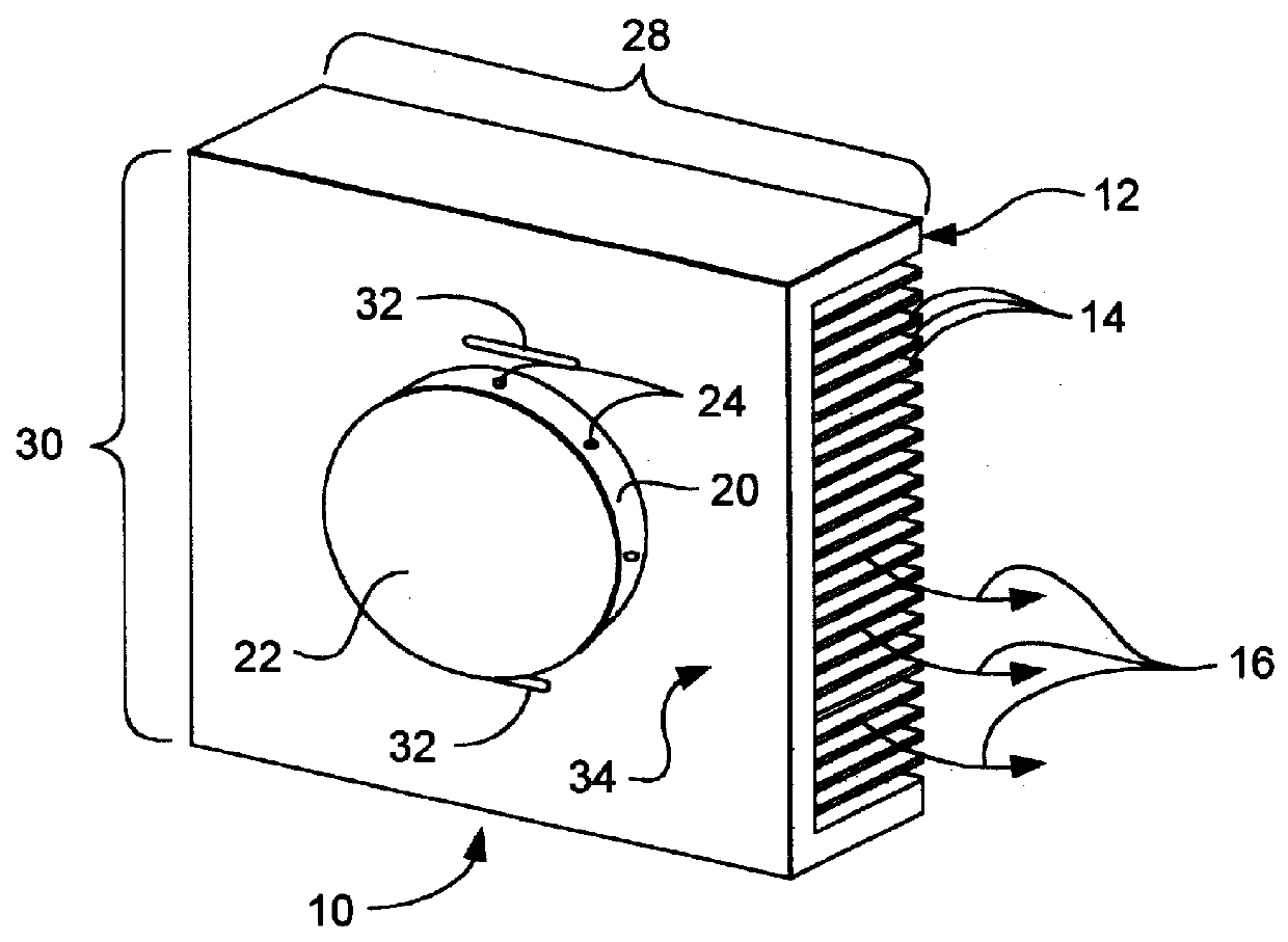
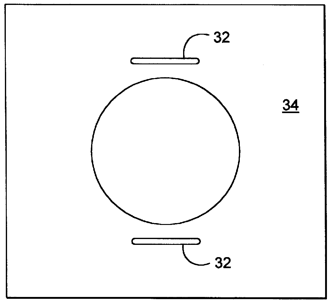
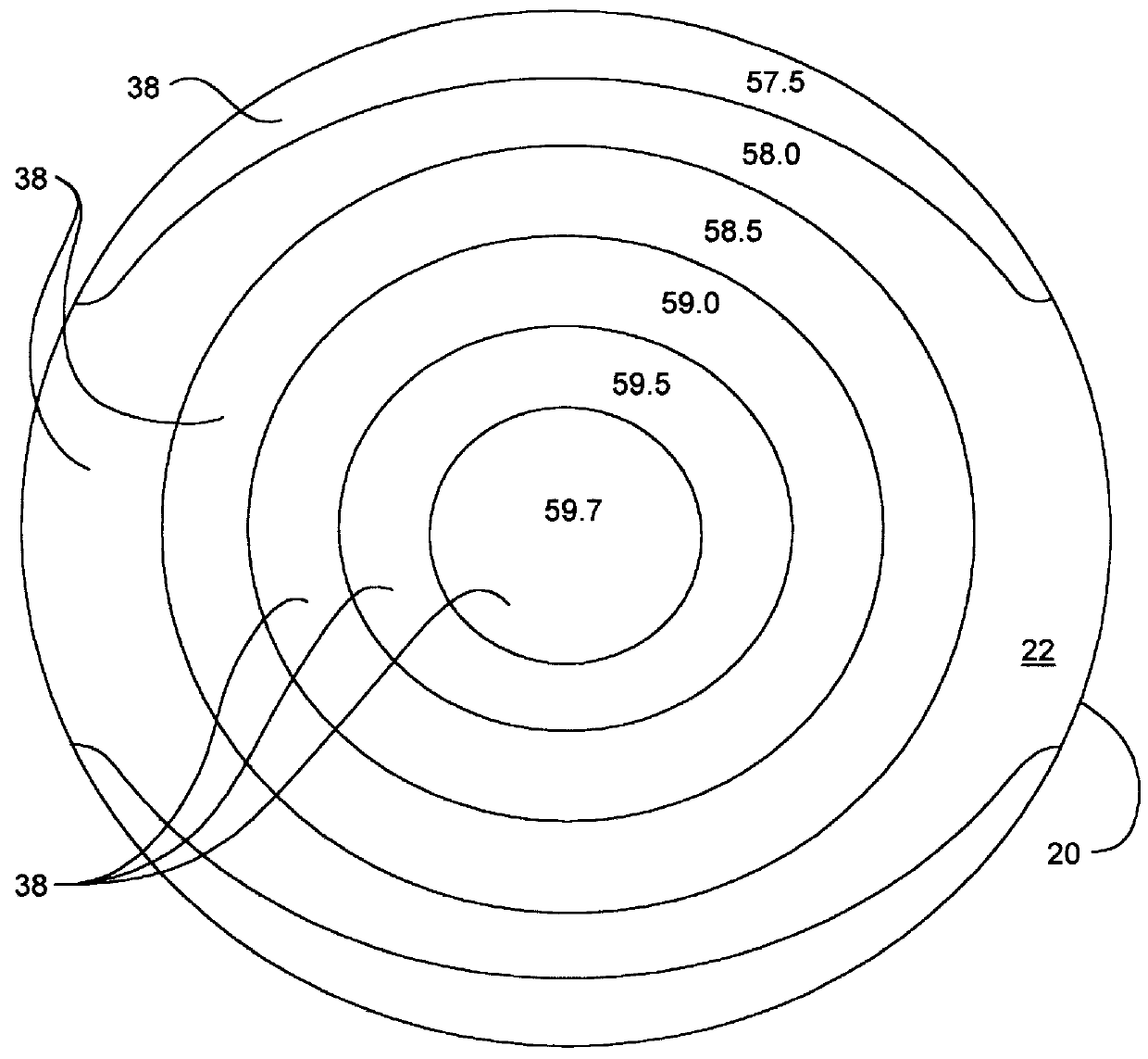
As shown in FIGS. 1-3, the thermal chuck or heat sink 10 has features specific to its task. Lower surface 12 is covered with fins 14 parallel to air flow 16, to increase the surface area and promote heat transfer. Air from the convection oven of a burn-in system, such as a modified form of the MTX system identified above, is ducted through these fins. The fins may be interrupted and staggered to further promote heat transfer. These fins may also also interrupted for access to various mechanical features necessary for the operation of the mechanism. The overall size and shape of the chuck are determined from space considerations in the existing oven configuration, in this case, the oven configuration of the MTX system. A wafer 18 rests on the upper surface of the chuck. The feature that it rests on is a circular raised portion or pedestal 20 of a diameter appropriate to the wafer 18 under test. Top surface 22 of this raised area is polished and lapped to a high degree of smoothness a...


PUM

PropertyMeasurementUnit
temperatureaaaaaaaaaa
aspect ratioaaaaaaaaaa

Abstract

A thermal chuck or heat sink (10) has a lower surface (12) covered with fins (14) parallel to air flow (16), to increase the surface area and promote heat transfer. A pair of slots (32) near pedestal (20) (along the fins) effectively lowers the conductivity of the metal in the direction across the fins. Heat flowing through this region of lowered conductivity experiences a greater temperature drop. This raises the temperature at the adjacent parts of the top surface, and (for properly sized slots) results in circular isotherms. The circular isotherms are turned into a nearly isothermal surface by a precisely dimensioned groove (36) parallel to the top surface (22), extending around the circumference of the pedestal (20). Heat flowing into the outer regions of the circular surface (22) is forced to travel radially inward, thus raising the edge temperature (which would naturally be lower than the center). For properly sized slots (32) and groove (36), it is possible to achieve a nearly constant temperature top surface (22).

Description

This following invention relates to a type of heat sink for cooling a fabricated integrated circuit wafer under power, referred to as a thermal chuck. Typically, the thermal chuck is used in a burn-in oven. This thermal chuck removes heat from the powered wafer and transfers it to the high temperature air circulating in the oven. This particular application demands that the surface the wafer rests on be isothermal (at a constant temperature). The invention further relates to a method of temperature control for a workpiece, such as an integrated circuit wafer under power during burn-in.After fabrication, many integrated circuits undergo the process of burn-in. An example of a burn-in system used for this purpose is disclosed in commonly assigned Brehm et al., U.S. Pat. No. 5,682,472, and is commercially available from the assignee under the designation MTX. In this process, the circuits are subjected to a variety of stresses outside their normal operating range to induce failures. Ci...

Claims


Application Information

Patent Timeline
Patent Type & Authority Patents(United States)
IPC IPC(8): H01L21/00G01R31/30G01R31/26H01L21/66H01L21/683
CPCH01L21/67248H01L21/67103H01L22/00
Inventor ANDBERG, JOHN W.
Owner AEHR TEST SYSTS
Why Eureka
Try Eureka