SRAM cell structure with dielectric sidewall spacers and drain and channel regions defined along sidewall spacers

a sram cell and dielectric sidewall technology, applied in the direction of semiconductor devices, electrical apparatus, transistors, etc., can solve the problems of reducing the overall cell size, the area of the cell, and the need for a larger footprint of the cell to achieve greater speed and stability

Inactive Publication Date: 2000-10-31
STMICROELECTRONICS SRL
View PDF81 Cites 56 Cited by
  • Summary
  • Abstract
  • Description
  • Claims
  • Application Information

AI Technical Summary

Problems solved by technology

However, a disadvantage of prior art SRAM cells is that such cells have required a larger footprint to achieve greater speed and stability than DRAM cells.
This problem is especially critical in SRAM devices where a typical individual memory cell contains as many as six separate components.
However, even with a split wordline memory cell design, a need remains to further reduce the overall cell dimensions.
Although split wordline designs reduce the area of the cell, fundamental manufacturing limitations remain.
However, downsizing of components can only be pursued to the limit of the lin

Method used


Image

  • SRAM cell structure with dielectric sidewall spacers and drain and channel regions defined along sidewall spacers
  • SRAM cell structure with dielectric sidewall spacers and drain and channel regions defined along sidewall spacers
  • SRAM cell structure with dielectric sidewall spacers and drain and channel regions defined along sidewall spacers

Examples


Embodiment Construction

The process steps and structures described herein do not form a complete process flow for manufacturing integrated circuits. The present invention can be practiced in conjunction with integrated circuit fabrication techniques currently used in the prior art, and only so much of the commonly practiced process steps are included as are necessary for an understanding of the present invention. The figures representing portions of an integrated circuit during fabrication are not drawn to scale but instead are drawn so as to illustrate the important features of the invention.

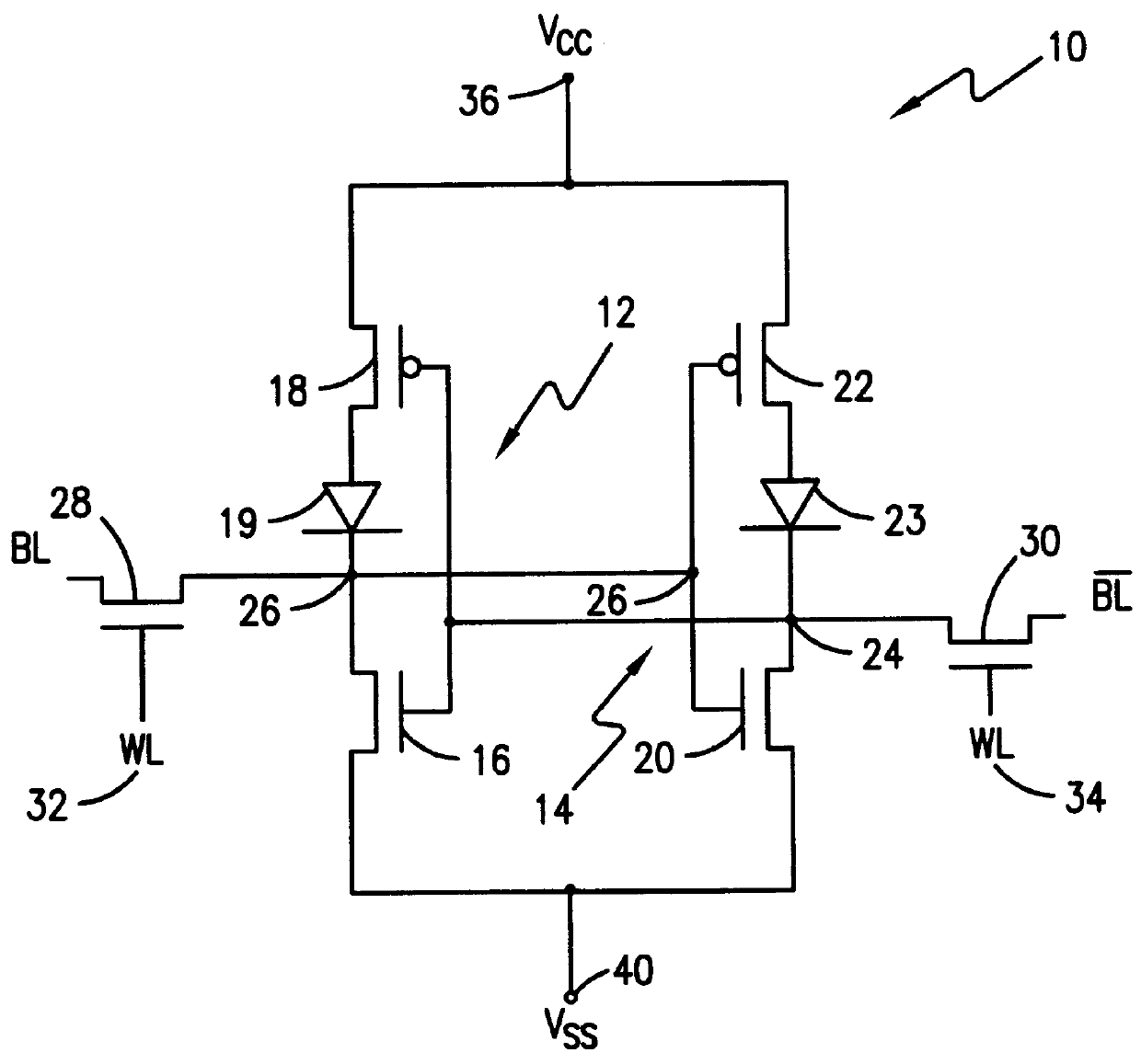
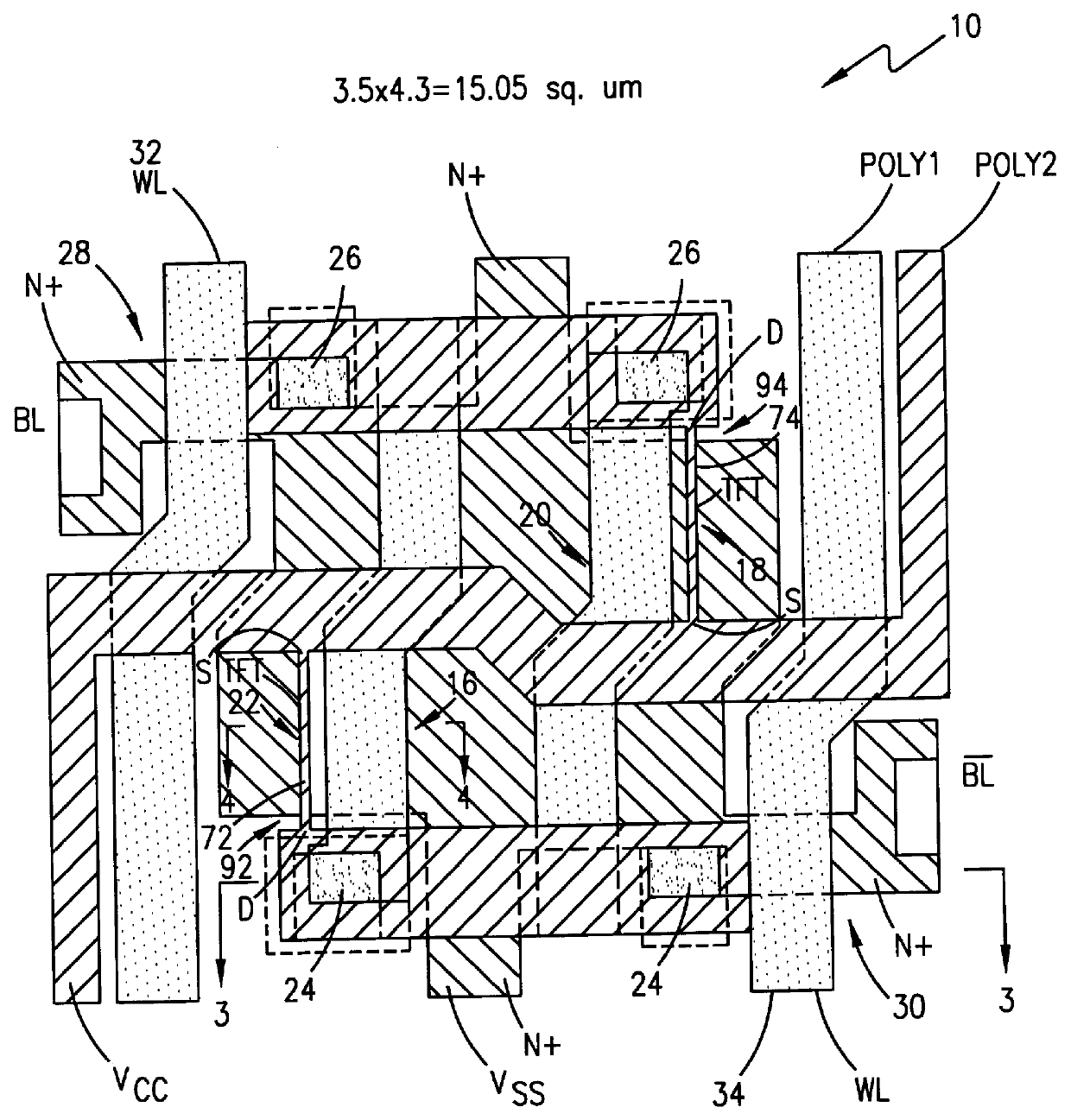
Referring now to FIG. 1, a schematic circuit diagram of an SRAM cell 10 according to the present invention is shown. Memory cell 10 is further illustrated in an MOS integrated circuit layout in accordance with the invention in FIG. 2. Memory cell 10 includes two cross-coupled, CMOS inverters 12 and 14. CMOS inverter 12 includes an NMOS driver transistor 16 and a PMOS thin-film, load transistor 18 fabricated in accorda...


PUM


Abstract

A six transistor static random access memory (SRAM) cell with thin-film pull-up transistors and method of making the same includes providing two bulk silicon pull-down transistors of a first conductivity type, two active gated pull-up thin-film transistors (TFTs) of a second conductivity type, two pass gates, a common word line, and two bit line contacts. The bulk silicon pull-down transistors, two active gated pull-up TFTs, and two pass gates are connected at four shared contacts. In addition, the two bulk silicon pull-down transistors and the two active gated pull-up TFTs are formed with two polysilicon layers, a first of the polysilicon layers (poly1) is salicided and includes poly1 gate electrodes for the two bulk silicon pull-down transistors. A second of the polysilicon layers (poly2) includes desired poly2 stringers disposed along side edges of the poly1 gate electrodes, the desired poly2 stringers forming respective channel regions of the pull-up TFTs.

Description

1. Field of the InventionThe present invention relates to semiconductor integrated circuit structures and methods of making such structures and, more particularly, to a method of making and structure of SRAM cells.2. Discussion of the Related ArtCMOS static random access memories (SRAM) are used in the semiconductor and computer industries as a result of the combination of speed, low power, and no requirement for refresh. Information can be written into and read out of an SRAM cell faster than with a DRAM cell, because the transistors of the SRAM cell can be switched faster than capacitors can be charged and drained. However, a disadvantage of prior art SRAM cells is that such cells have required a larger footprint to achieve greater speed and stability than DRAM cells.As semiconductor devices become smaller, it becomes necessary to arrange individual components within a device such that minimal separation distances are achieved. The need to design compact component arrangements occ...

Claims


Application Information

Patent Timeline
IPC IPC(8): H01L21/70H01L27/11H01L21/8244H01L29/786
CPCH01L27/11H01L27/1108Y10S257/903H10B10/00H10B10/125
Inventor CHAN, TSIU CHIUBRYANT, FRANK RANDOLPH
Owner STMICROELECTRONICS SRL
Why Eureka
Try Eureka