Disk drive with controlled reduced internal pressure

a technology of internal pressure and disk drive, which is applied in the direction of motor/generator/converter stopper, dynamo-electric converter control, instruments, etc., can solve the problems of excessive power consumption, difficult for the read/write head to locate the proper data track, and excessive heat in the disk drive housing, etc., to achieve reduced internal pressure, reduced pressure, and increased rpm

Inactive Publication Date: 2000-11-07
HITACHI GLOBAL STORAGE TECH NETHERLANDS BV
View PDF6 Cites 75 Cited by
  • Summary
  • Abstract
  • Description
  • Claims
  • Application Information

AI Technical Summary

Benefits of technology

The present invention is a rigid magnetic recording disk drive that includes a vacuum pump attached to the disk drive housing for removing air from within the housing so that the disk drive is operated at a reduced internal pressure. The pump motor is controlled by control circuitry that receives an input signal representative of the pressure within the disk drive to enable the disk drive pressure to be maintained within a predetermined reduced pressure range. In the preferred embodiment a signal representative of the spindle motor current is used as the input to the pump control circuitry. The pump control circuitry receives as input from the disk drive controller an IDLE signal (or a HEAD UNLOADED signal if the disk drive is a head load / unload type) to prevent the pump from turning on when the disk drive is reading or writing data. Means are also provided for preventing the pump from turning until the spindle motor has reached its stable operating speed. As an alternative to the spindle motor current input signal, a pressure sensor is located within the disk drive housing and provides an input signal to the pump control circuitry for turning the pump on and off to maintain the desired reduced pressure within the disk drive housing. The pump and pump motor are located in a cut-out on the exterior of the disk drive housing or within a walled-in recess of the housing so that the housing form factor is not altered, thereby allowing the disk drive with the present invention to fit into conventional computer bays. With the present invention the disk drive operates at a significantly higher RPM with only a minimal increase in power consumption and without any increase in TMR.

Problems solved by technology

However, when conventional disk drives, such as commercially available 3.5 inch and 2.5 inch form factor drives, are rotated at high RPM they consume excessive power and generate excessive heat in the disk drive housing.
In addition, high speed disk rotation causes airflow-induced disk "flutter" and vibration of the suspension and / or arm, which makes it difficult for the read / write head to locate the proper data track.

Method used


Image

  • Disk drive with controlled reduced internal pressure
  • Disk drive with controlled reduced internal pressure
  • Disk drive with controlled reduced internal pressure

Examples


Embodiment Construction

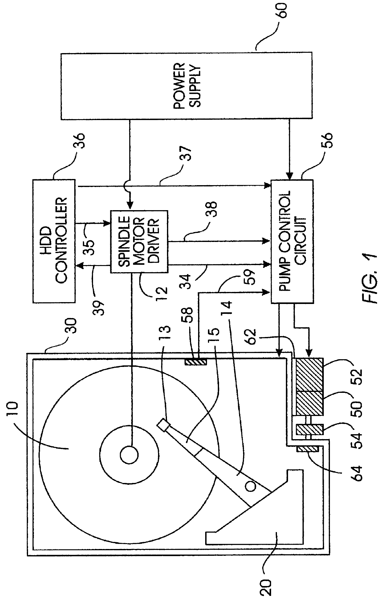
A disk drive incorporating the present invention is shown schematically in FIG. 1.

A magnetic recording disk 10 is mounted on the drive or spindle motor (not shown) that is controlled by the electronic circuitry of spindle motor driver 12. A read / write head carrier 13 is positioned on the top surface of disk 10. Carrier 13 is an air-bearing slider having an air-bearing surface facing toward the disk. The head carrier 13 supports a read / write transducer or head for reading and writing data to the magnetic media on the surface of disk 10. The head may be an inductive read / write head or a dual element head having an inductive write element and a magnetoresistive read element. Carrier 13 is attached to an actuator arm 14 by means of a suspension 15. The suspension 15 provides a slight spring force that biases the carrier 13 toward the disk surface.

Actuator arm 14 is attached to a rotary actuator 20. The actuator is typically a rotary voice coil motor (VCM) that comprises a coil movable w...


PUM

PropertyMeasurementUnit
pressureaaaaaaaaaa
pressureaaaaaaaaaa
pressureaaaaaaaaaa

Abstract

A rigid magnetic recording disk drive includes a vacuum pump attached to the disk drive housing for removing air from within the housing so that the disk drive is operated at a reduced internal gas pressure. The pump motor is controlled by control circuitry that receives an input signal representative of the pressure within the housing to enable the pressure to be maintained within a predetermined reduced pressure range. Because spindle motor current has been directly correlated with internal pressure, a signal representative of the spindle motor current is used as the input to the pump control circuitry. The pump control circuitry also prevents the pump from turning on until the spindle motor has reached its stable operating speed, and from turning on when the disk drive is reading or writing data. Because of the reduced internal pressure the disk drive operates at a significantly higher disk RPM with only a minimal increase in power consumption and without any increase in track misregistration.

Description

TECHNICAL FIELDThis invention relates in general to magnetic recording disk drives, and more particularly to magnetic recording rigid disk drives with high speed spindle motor rotation.BACKGROUND OF THE INVENTIONDisk drives, also called disk files, are information storage devices that use a rotatable rigid disk with concentric data tracks containing the information, a head or transducer for reading and / or writing data onto the various tracks, and an actuator connected to a carrier for the head for moving the head to the desired track and maintaining it over the track centerline during read and write operations. The most common form of actuator is a rotary voice coil motor (VCM) actuator that moves the head carrier in a nonlinear, generally arcuate path across the disk. There are typically a number of disks mounted on a hub that is rotated by a disk drive motor, also called a spindle motor, and a number of head carriers connected to the actuator for accessing the surfaces of the disk...

Claims


Application Information

Patent Timeline
Patent Type & Authority Patents(United States)
IPC IPC(8): G11B33/14
CPCG11B33/1486
Inventor HIRANO, TOSHIKISATOH, KIYOSHI
Owner HITACHI GLOBAL STORAGE TECH NETHERLANDS BV
Why Eureka
Try Eureka