The fuel
injection pump according to the invention, has the
advantage over the prior art that the pressure compensation surface according to the invention produces a compensation force that is independent of the rotational position of the moving part since the pressure compensation surface always remains intrinsically closed. The pressure that prevails in the region of the pressure compensation surface and is diverted by the output pressure of the high-pressure source to the adjoining outlet opening can be adjusted by
dimensioning the first and second leakage routes in the desired fashion. This embodiment also has the
advantage that with the
high pressure that occurs in the region of the outlet opening as a result of the intermittently occurring high-pressure fuel injection, due to the deformation of the moving part on the one hand and of the housing bore on the other hand, the magnitude of the leakage routes, in particular their effective through flow cross section, is influenced so that an outflow cross section by way of the second leakage route is reduced and an inflow cross section by way of the first leakage route is increased. As a result, in the region of the pressure compensation surface, the pressure increases superproportionally with increasing
high pressure. This pressure, which tends to increase more rapidly, produces a correspondingly higher compensation force counter to the force that is produced in the region of the outlet opening with the high-
pressure increase. The lateral force resulting from the sum of the forces therefore only increases slowly as the
pressure level of the high-pressure source rises. On the other hand, the compensation force decreases the deformation on the moving part and the housing bore containing it. In the moving part, these deformations are flattenings of the circular cross section in the direction of an elliptical cross section and in the housing bore, they are bore widenings, likewise with an elliptical cross section, wherein the main axes of the respective cross sections are disposed perpendicular to each other. With a reduction of this deformation, lesser lateral contractions or lateral widenings also occur lateral to the deformations being produced so that a smaller play between the moving part and the housing bore can be achieved in the fundamental
dimensioning of these parts in relation to each other. With the reduction of this play, the quantity balance of the high-
pressure injection improves by virtue of the fact that the leakage losses that arise by way of this play are reduced. This occurs with an even more reliable operation without the danger that by means of a play that is in turn too narrow, an excessive
surface pressure occurs between the parts associated with each other, with the result of a
seizing of the moving part in the housing bore.
In an advantageous embodiment, the second leakage route is essentially twice as long as the first leakage route, which produces a favorable quantity balance of high-pressure fuel flowing toward the pressure compensation surface and fuel flowing away again from this pressure compensation surface to a relief chamber. The pressure occurring in the region of the pressure compensation surface can be adjusted with the length of the leakage routes and the cross sections that occur.
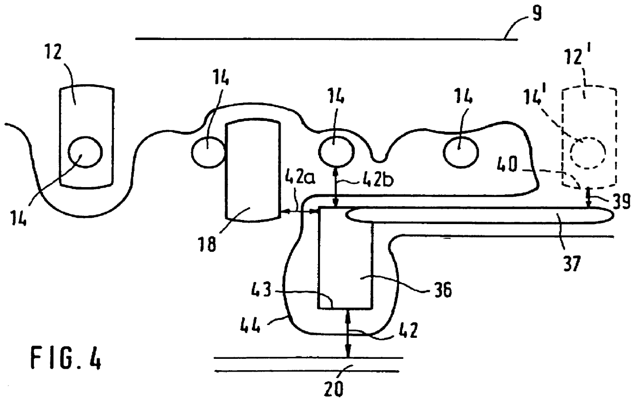
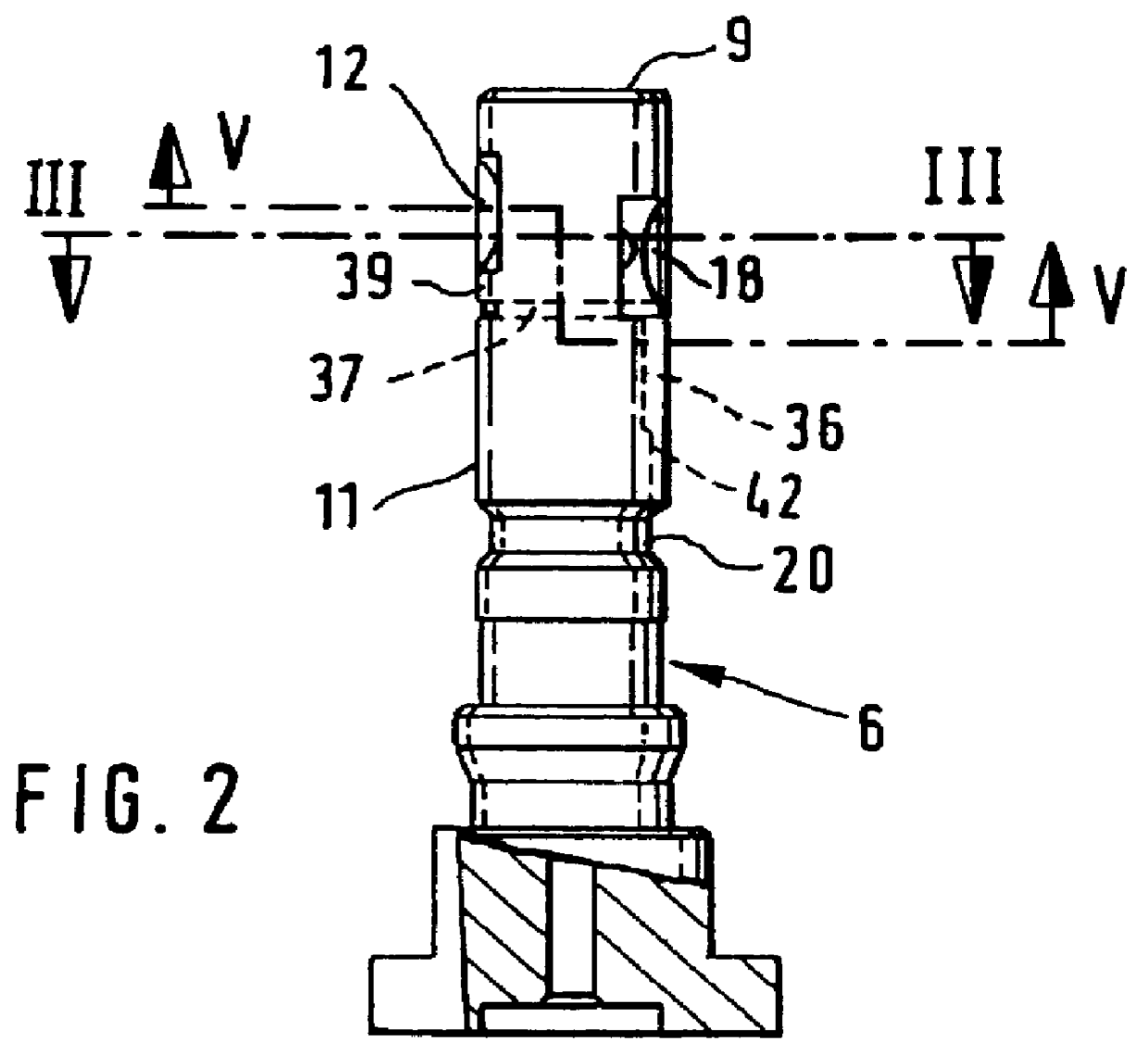
In a known manner, the distributor opening is embodied as a longitudinal groove, wherein, the continuing groove that leads from the pressure compensation surface is embodied as a partial annular groove, which ends in the axial direction above or below the distributor longitudinal groove and defines the first leakage route there. The second leakage route is formed by the pressure compensation surface and a conduit that likewise extends in the circumferential direction and is connected to a relief chamber of the fuel
injection pump. According to the invention, a number of pressure compensation surfaces are advantageously provided, wherein, the surface area of the pressure compensation surface is advantageously greater than the surface area of the outlet opening that is directly acted on by the
high pressure of the high-pressure fuel source.
For the intentional positioning of the pressure compensation surface or for the
accommodation of a number of pressure compensation surfaces in desired circumference regions of the moving part, the pressure compensation surfaces are advantageously embodied as a longitudinal groove or a flattening or ground surface that extends in a longitudinal direction in relation to the axis of the rotating, moving part. The pressure field in the region of the pressure compensation surface can advantageously be defined by means of the length of this longitudinal groove and a pressure compensation surface of this kind must be accommodated in a manner that facilitates the manufacture and implementation, between otherwise existing high pressure-carrying grooves or pressure relief grooves in the region of the jacket face of the moving part.
In an advantageous manner, a continuing groove is provided, which is chiefly used for adjusting the desired gap length in regions of the jacket face that are favorable for this adjustment. The pressure compensation surface can be disposed in a relatively isolated manner far from the high pressure-carrying outlet opening and can nevertheless reach a desired proximity to this outlet opening by way of the continuing groove or groove-like flattening in order to define the first leakage route there. Correspondingly, a leakage route length to a relief side can also be adjusted by way of this continuing groove.
In a known manner, the distributor opening is embodied as a longitudinal groove, wherein, the continuing groove that leads from the pressure compensation surface is embodied as a partial annular groove, which ends in the axial direction above or below the distributor longitudinal groove and defines the first leakage route there. The second leakage route is formed by the pressure compensation surface and a conduit that likewise extends in the circumferential direction and is connected to a relief chamber of the fuel injection pump. According to the invention, a number of pressure compensation surfaces are advantageously provided, wherein, the surface area of the pressure compensation surface is advantageously greater than the surface area of the outlet opening that is directly acted on by the high pressure of the high-pressure fuel source.
In a known manner, the distributor opening is embodied as a longitudinal groove, wherein, the continuing groove that leads from the pressure compensation surface is embodied as a partial annular groove, which ends in the axial direction above or below the distributor longitudinal groove and defines the first leakage route there. The second leakage route is formed by the pressure compensation surface and a conduit that likewise extends in the circumferential direction and is connected to a relief chamber of the fuel injection pump. According to the invention, a number of pressure compensation surfaces are advantageously provided, wherein, the surface area of the pressure compensation surface is advantageously greater than the surface area of the outlet opening that is directly acted on by the high pressure of the high-pressure fuel source.
