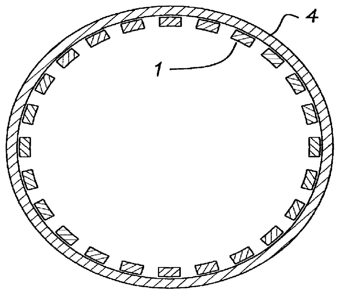
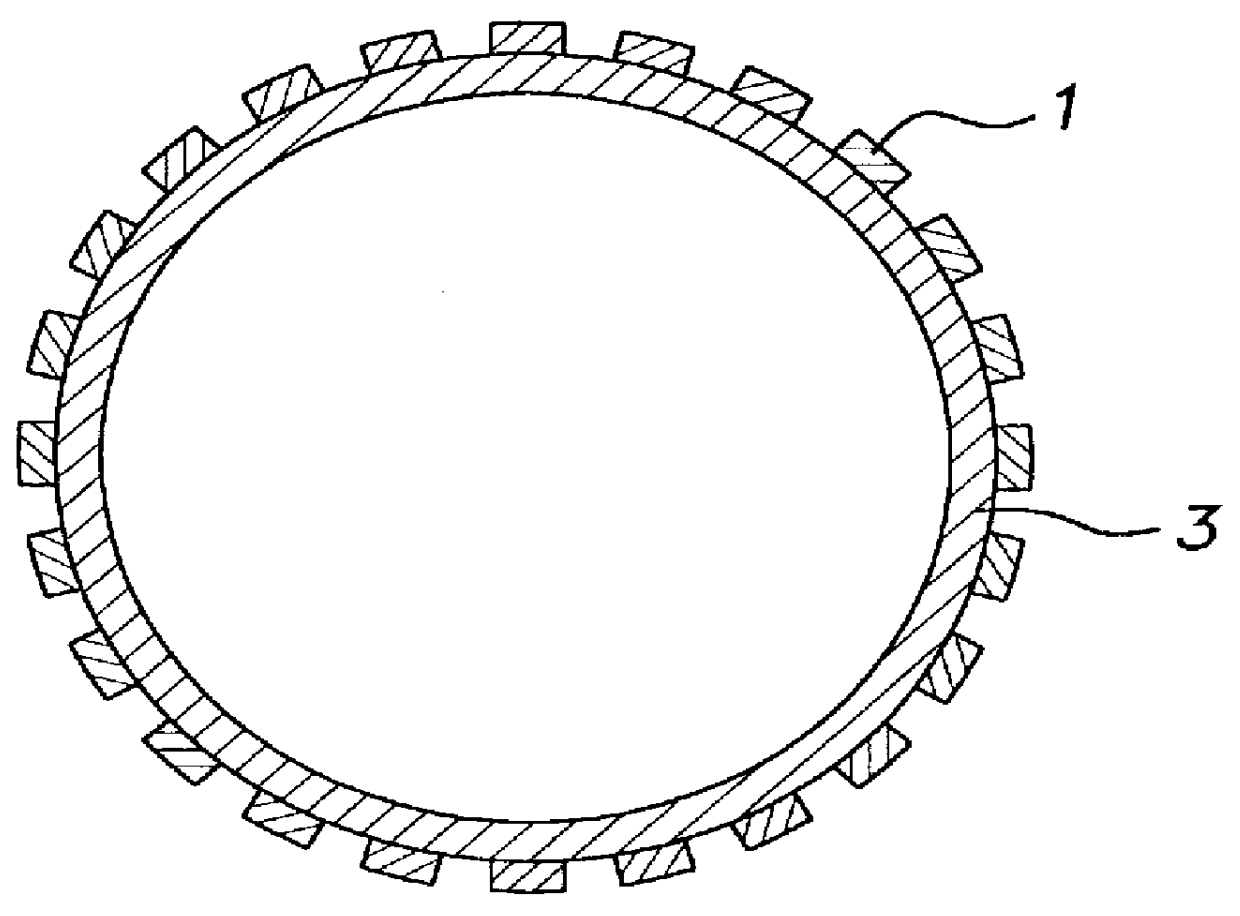
(1) A plurality of superconducting wire material units each of which is fixed onto a cylindrical support member and each of which is composed of a single tape-like oxide superconducting wire material or a laminated tape-like oxide superconducting wire material, such that the tape surfaces of the superconducting wire material units are disposed in parallel with a circumferential direction In a
cylindrical coordinate system. By this measure, the main component of the self
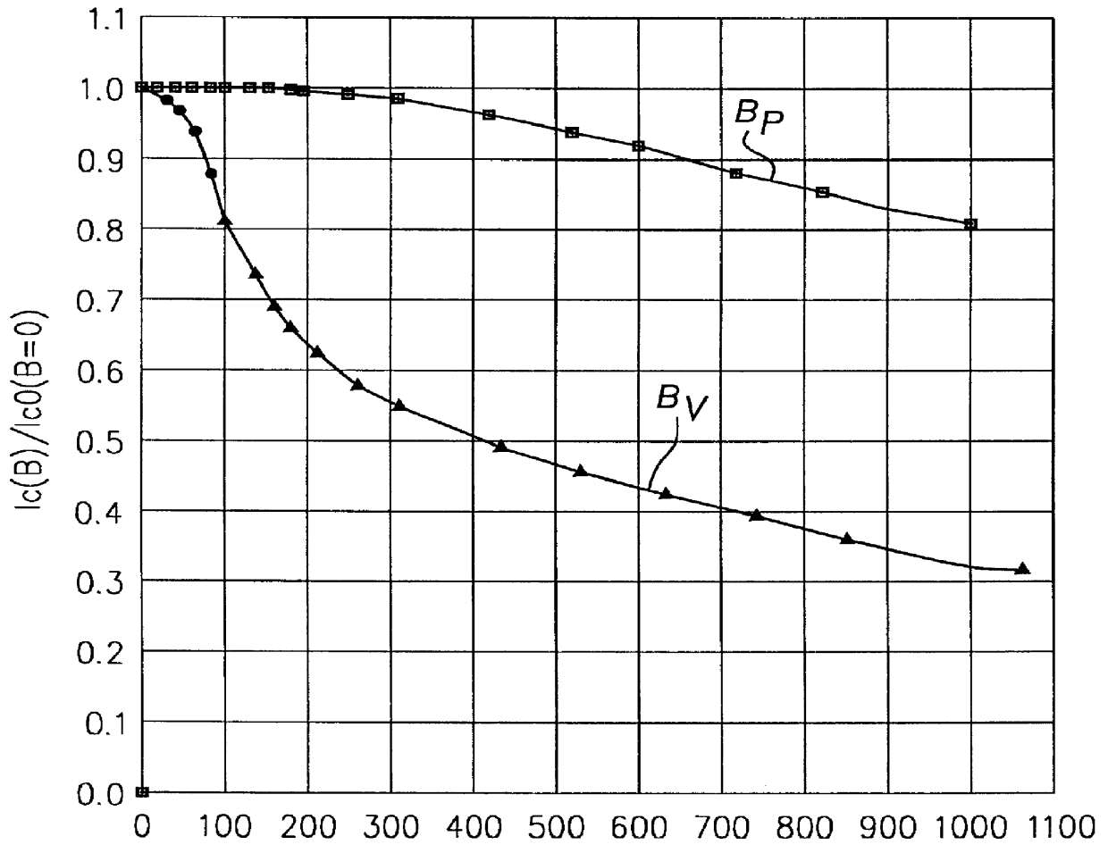
magnetic field generated by the self current is parallel with the tape surfaces of the superconducting wire materials. Accordingly, the
magnetic field components perpendicular to the tape surfaces are reduced so that the lowering of the
critical current value due to the self magnetic field can be reduced. Further, because the tape surfaces of the superconducting wire material units such as silver sheath superconducting wire material units, or the like, are fixed securely in the circumferential direction by the support member, the self magnetic field generated is not disordered so that the
critical current value can be kept as designed. Further, the cylindrical support member is formed from a low
thermal conductivity material. By this measure, the quantity of penetration of heat into the low temperature portion can be reduced.
(2) A plurality of superconducting wire material units each of which is fixed onto a cylindrical support member and each of which is composed of a single tape-like oxide superconducting wire material or a laminated tape-like oxide superconducting wire material, such that the tape surfaces of the superconducting wire material units are disposed in parallel with a circumferential direction in a
cylindrical coordinate system. By this measure, the main component of the self magnetic field generated by the self current becomes parallel with the tape surfaces of the superconducting wire materials. Accordingly, the magnetic field components perpendicular to the tape surfaces are reduced so that the lowering of the critical current value due to the self magnetic field can be reduced. Further, because the tape surfaces of the superconducting wire material units such as silver sheath superconducting wire material units, or the like, are fixed securely in the circumferential direction by the support member, the self magnetic field generated is not disordered so that the critical current value can be kept as designed.
Here, a magnetic material is used as the support member. By this measure, harmful magnetic field components which are perpendicular to the tape surfaces and which cause the lowering of the critical current value due to the self magnetic field generated by the self current in the superconductors can be reduced more greatly through the magnetic material.
(3) Further, in the superconducting current lead described in the
paragraph (2), the support member is configured so that a magnetic material is disposed on its high temperature side, and a low thermal
conductivity material is disposed on its low temperature side and connected to the magnetic material. By this measure, not only the magnetic field components perpendicular to the tape surfaces can be reduced to keep the critical current value high but also the quantity of penetration of heat into the low temperature side can be suppressed.
(4) Further, in the superconducting current lead described in the
paragraph (2), the support member is disposed on the outer circumferential side of the superconducting wire material units so as to surround the superconducting wire material units. By this measure, the magnetic field components perpendicular to the tape surfaces can be reduced more effectively to make it easy to keep the critical current value high.
(5) Further, in the superconducting current lead described in any one of the paragraphs (1) through (4), a magnetic material is disposed so as to surround the support member and the superconducting wire material units each of which is composed of a single tape-like oxide superconducting wire material or a laminated tape-like oxide superconducting wire material. By this configuration, the tape surfaces of the superconducting wire materials are fixed securely in the circumferential direction by the support member. Accordingly, the self magnetic field generated is not disordered so that the self magnetic field generated to be perpendicular to the tape surfaces can be reduced greatly through the magnetic material disposed in the outer circumference. By this measure, the critical current value can be kept free from deterioration.

