

Method of making a coated planet gear journal bearing
- Summary
- Abstract
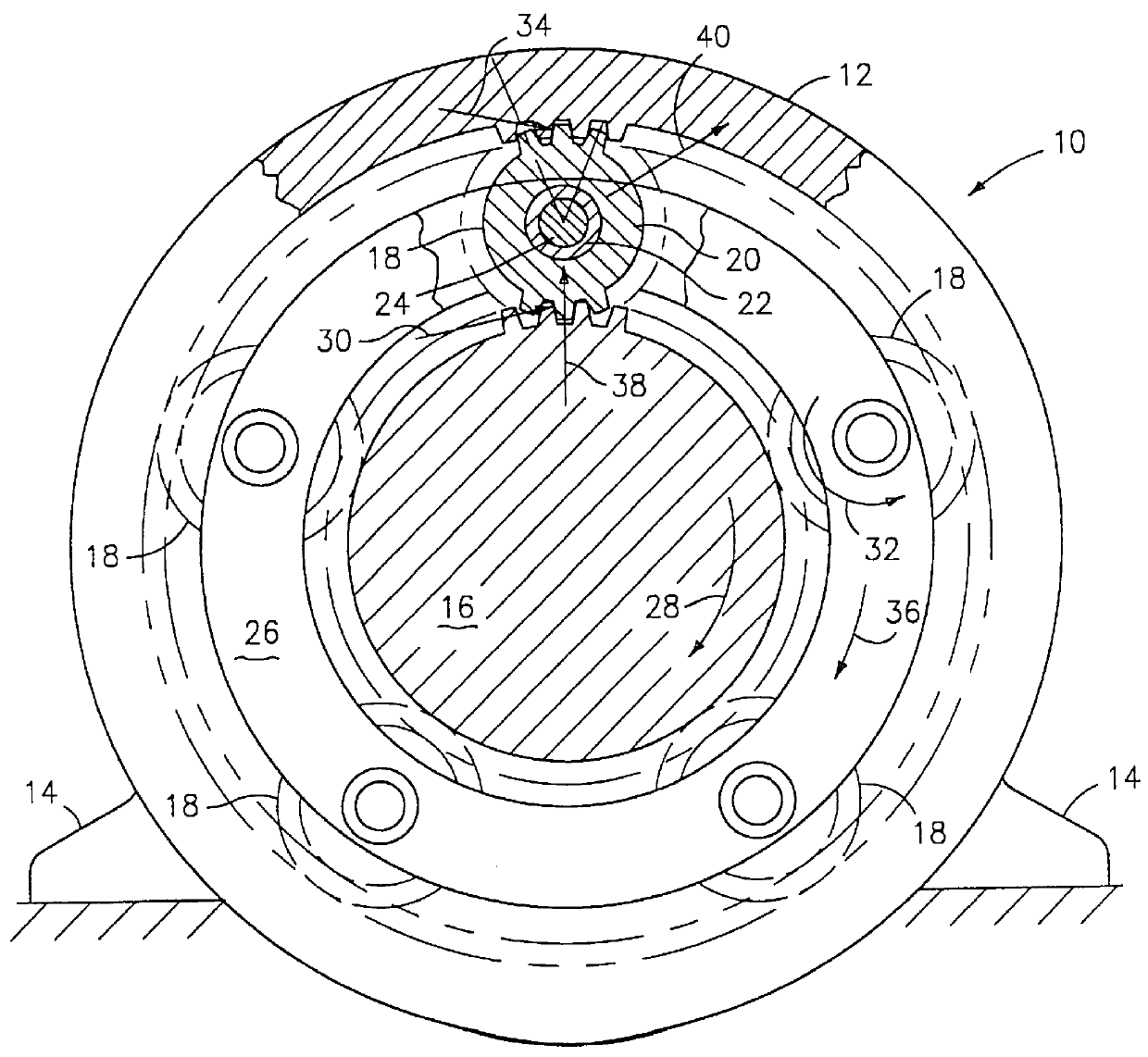
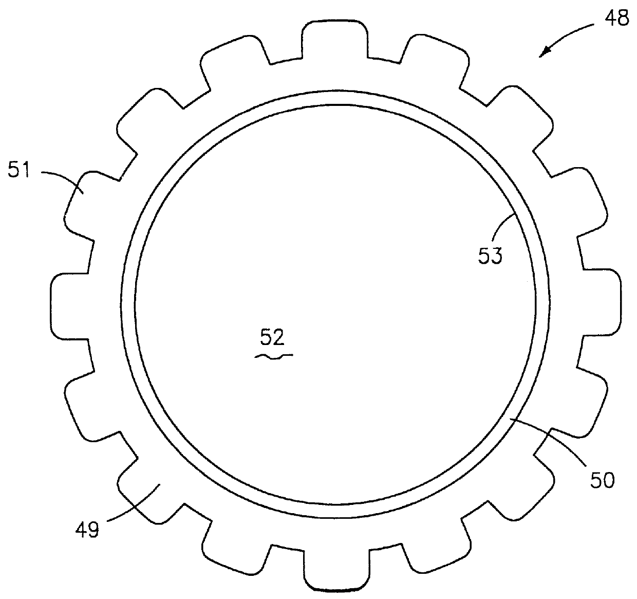
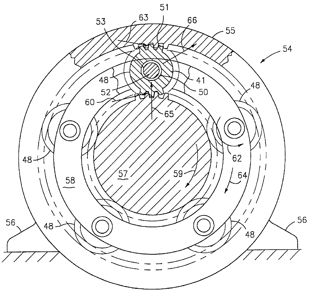
- Description
- Claims
- Application Information
AI Technical Summary
Benefits of technology
Problems solved by technology
Method used
Image

Examples
example 2
A coated planet gear according to the present invention and a prior art gear were tested in a gear test rig. The rig simulates the environment the planet gears would be subjected to when integrated into a planetary gear system. Full-scale component testing confirmed that a lightweight sputtered planet gear performs at least as well as the conventional cast bearing sleeved gear. This is an unexpected result given that the sputtered planet gear achieves this while at the same time reducing the weight of the system. Weight reductions of at least 25% are achievable since the sputtered planet gear is smaller than the sleeved planet gear, has a smaller gear pitch diameter and thus provides a smaller and therefore lighter gear system.
The full-scale gear bore was sputter coated in a vacuum at temperatures up to 570.degree. F. The sputtering rate was approximately 0.05 in.sup.3 / hr. Component rig testing was conducted for both the conventional cast bearing sleeved gear and the sputtered gear...
PUM
| Property | Measurement | Unit |
|---|---|---|
| Fraction | aaaaa | aaaaa |
| Fraction | aaaaa | aaaaa |
| Thickness | aaaaa | aaaaa |
Abstract
Description
Claims
Application Information