Apparatus for producing high density slurry and paste backfills

a technology of slurry and paste, which is applied in the direction of soil preservation, settling tank feed/discharge, sedimentation settling tank, etc., can solve the problems of high maintenance cost, high environmental impact of alluvial sand excavation,

Inactive Publication Date: 2001-01-02
HER MAJESTY THE QUEEN & RIGHT OF CANADA REPRESENTED BY THE MIN OF NATURAL RESOURCES
View PDF34 Cites 35 Cited by
  • Summary
  • Abstract
  • Description
  • Claims
  • Application Information

AI Technical Summary

Problems solved by technology

While the sand is used in the process to try to achieve a higher strength due to the particle size of the sand, excavation of alluvial sand raises environmental issues.
The main drawbacks associated with this system are that the thickeners are very costly, i.e. up to $1,000,000 each; being mechanical devices, they require a high level of maintenance; due to the various factors which can affect the thickening process, the fill plant operator must be consistent in judging the release time of the fill from the thickener; thickeners are large and require considerable floor space; and the energy costs to operate such thickeners are relatively high.
While the initial cost of a drum filter system is much lower than that of a thickener, the

Method used


Image

  • Apparatus for producing high density slurry and paste backfills
  • Apparatus for producing high density slurry and paste backfills
  • Apparatus for producing high density slurry and paste backfills

Examples


first embodiment

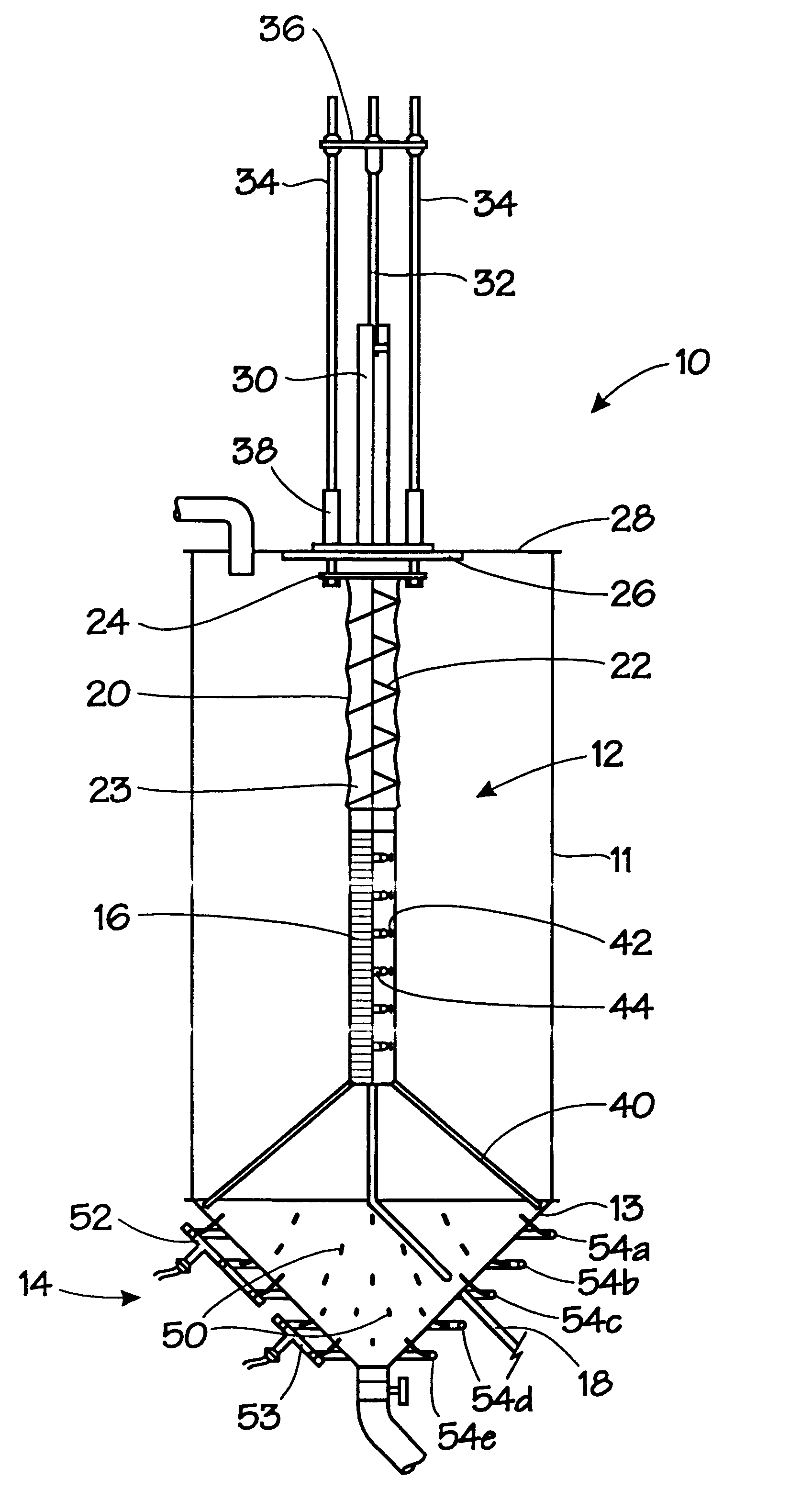
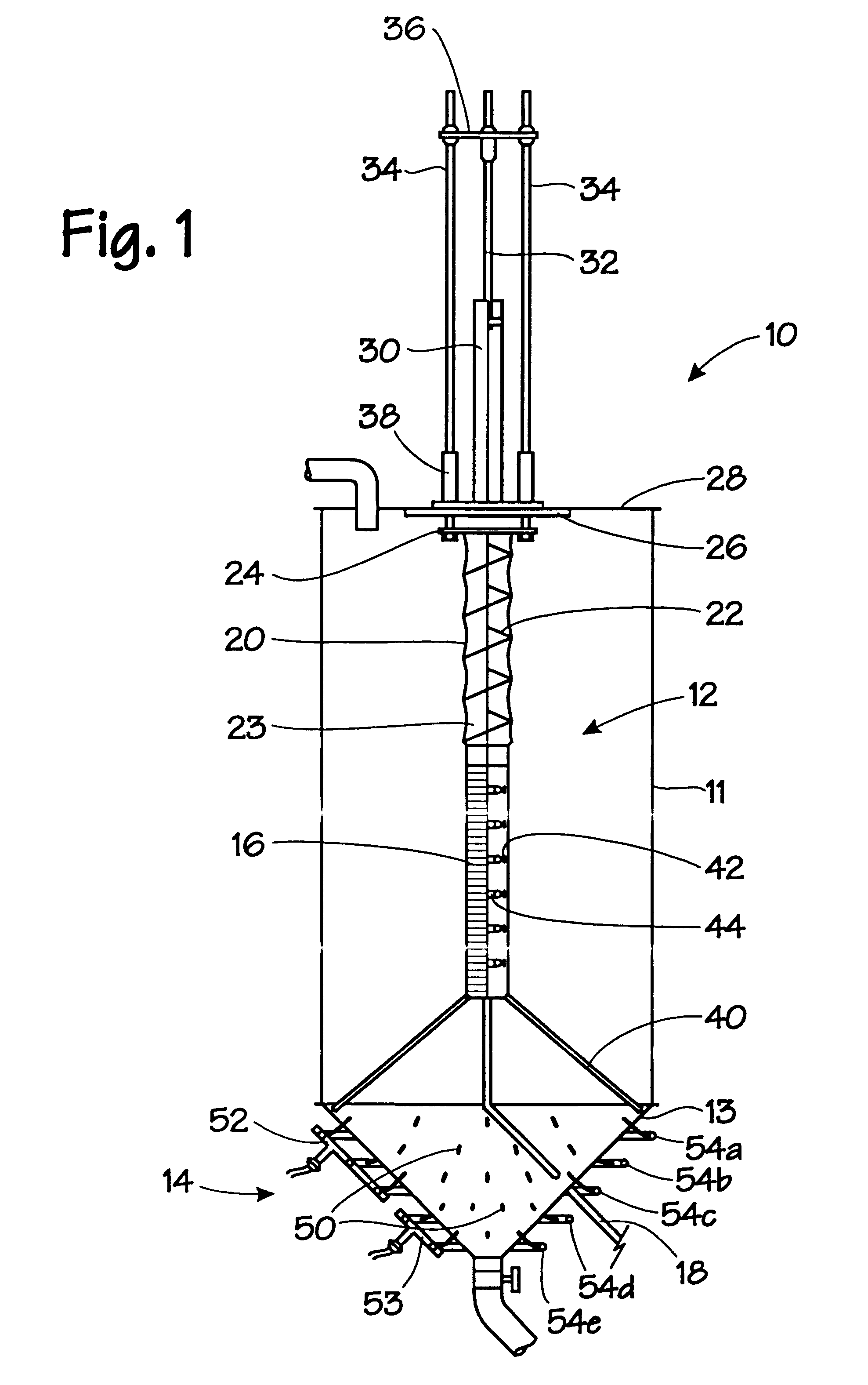
Above the screen 16 is the decant portion 20 of the device. In general, the decanter 20 is an adjustable length conduit which extends above the screen 16. In the first embodiment, a light coil spring 22 is attached at one end to the top of the percolation screen 16 and the other end to an annular plate 24. The plate 24 has an aperture through which the surface water may be decanted. The spring 22 is covered preferably with a 1 / 2" thick, rubber-like material 23, such as LINATEX.TM. brand.

The annular plate 24 may be raised and lowered by any form of suitable activation means. As shown in FIG. 1, a pneumatic or hydraulic cylinder 30 is used as the activation means for the decanter 20. A pneumatically operated system is actually preferred since a source of compressed air is already needed for use with the agitation / fluidization system 14. The pneumatic cylinder 30 is mounted by way of a mounting plate 26 to the upper closure 28 of the silo 11. The cylinder piston 32 is attached to a ser...

second embodiment

the integral containment vessel and high density slurry paste production apparatus is shown in FIG. 5 and generally denoted by reference numeral 210. The apparatus 210 is similar to the unit 10 illustrated in FIG. 1 (and may be substituted for the unit(s) 10 in the high density slurry or paste backfill production facilities of FIGS. 3 and 4), with the primary difference being that the percolation / decant insert 12 of the FIG. 1 unit 10 is replaced by separate percolation and decant apparatuses 220, 216 which perform generally the same respective functions. In addition, a feed cone 221 is provided at the top of the silo 211 which includes a feed well 225 disposed generally centrally thereof for introducing the raw slurry material. Details of the feed cone 221 and the feed well 225 are illustrated in FIGS. 6 and 7.

As with the silo 11 of the unit shown in FIG. 1, the shape and configuration of the silo body 211 and the bottom discharge cone 213 can be the same. Preferably, the silo body...


PUM

PropertyMeasurementUnit
Angleaaaaaaaaaa
Angleaaaaaaaaaa
Pressureaaaaaaaaaa

Abstract

An apparatus for producing high density slurry and paste backfills for use, for example, in mining operations. The high density slurry or paste is produced from a mill tailings mixture in a silo which includes a percolation and decant apparatuses for percolating water out of the mill tailings mixture and for decanting clarified water from atop the settled tailings. While settling occurs, air is introduced from the bottom of the silo to agitate the mixture to ensure substantially homogeneous settlement of the solids. Once settled, the resultant high density slurry or paste is fluidized by air in order to give the paste more readily flowable characteristics.

Description

The invention relates to a method and apparatus for producing high density slurry and paste backfills for use in mining operations and to backfill paste production facilities which incorporate the aforesaid method and apparatus.There are many different reasons for using backfilling in mines and not only to the benefit of the environment. In some cases, creating an opening underground poses no problem other than with the disposal of waste materials. However, in most types of rock, when an opening is created, it causes stress realignment around the opening. This not only creates problems with spalling and rock falls during rockbursts but also limits the size of the opening that can be made.Some of the reasons backfill is used in mines (not in any specific order):(a) to keep highly stressed rock around an opening from spalling. Spalling not only dilutes the ore but it can cause hazards in stopes where people are working;(b) to keep negatively stressed rock (in tension) around an openin...

Claims


Application Information

Patent Timeline
IPC IPC(8): B28C9/00
CPCB28C9/004
Inventor CHEN, LONG JINMILLETTE, DANIEL G.ANNOR, ALFRED
Owner HER MAJESTY THE QUEEN & RIGHT OF CANADA REPRESENTED BY THE MIN OF NATURAL RESOURCES
Why Eureka
Try Eureka