
Catalyst deterioration detecting apparatus for internal combustion engine

a technology of deterioration detection and internal combustion engine, which is applied in the direction of machines/engines, hybrid vehicles, electrical control, etc., can solve the problems of difficult to determine the deterioration of catalysts with high precision, degrade the performance of emission control, and difficult to maintain good emission quality

Inactive Publication Date: 2001-01-16
TOYOTA JIDOSHA KK
View PDF14 Cites 64 Cited by
  • Summary
  • Abstract
  • Description
  • Claims
  • Application Information

AI Technical Summary

Benefits of technology

Therefore, the catalyst deterioration detecting apparatus performs the catalyst deterioration determination after verifying that the catalyst has stored oxygen substantially up to the limit of the oxygen storing capacity of the catalyst, so that the determination can be performed with high precision.
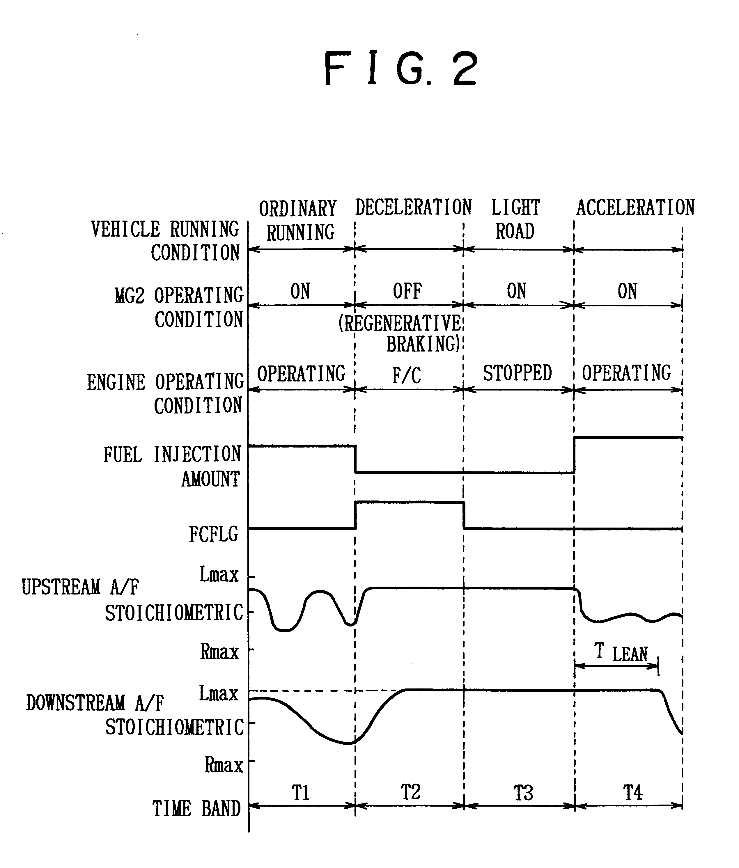
In this case, the catalyst deterioration determination is performed based on the time duration between the forced switching of the air-fuel ratio upstream of the catalyst to the rich side and the switching of the air-fuel ratio downstream of the catalyst from the lean side to the rich side, that is, the time duration up to the beginning of release of oxygen from the catalyst. Therefore, the catalyst deterioration determination can be performed within a short time. Furthermore, the degree of deterioration can be quantitatively determined.
If the internal combustion engine is stopped when the catalyst atmosphere contains an excess amount of oxygen, transfer of heat from the catalyst to the outside of the catalyst by exhaust gas is considerably reduced, so that the decreasing rate of the catalyst temperature becomes small. As a result, a condition in which an excess amount of oxygen is present near the catalyst and the catalyst has a relatively high temperature that allows the catalyst to store oxygen is maintained. Therefore, the catalyst stores oxygen up to the maximum oxygen adsorbing capacity even during a stop of the internal combustion engine.

Problems solved by technology

If the oxygen storage function of the catalyst deteriorates, the emission control performance becomes degraded.
That is, hydrocarbons and carbon monoxide are let out to the downstream side of the catalyst, so that maintenance of good emission quality becomes difficult.
However, in such case, it is difficult to determinate a deterioration of a catalyst with high precision.
The reason is that if the engine fuel cut is continued for a long time, the temperature of the catalyst is decreased so that the catalyst cannot store oxygen up to the maximum oxygen adsorbing capacity thereof even in the presence of an excess amount of oxygen.
Conversely, if the fuel cut duration is short, there is not provided a time needed for sufficient adsorption of oxygen to the catalyst.
In such cases, an excessive degree of deterioration of the catalyst is detected although the amount of oxygen stored in the catalyst is less than the maximum oxygen adsorbing capacity of the catalyst, so that the determination regarding deterioration of the catalyst may not be performed with high precision.
Furthermore, an atmosphere around the catalyst may be caused to contain an excess amount of oxygen before the internal combustion engine is temporarily stopped.

Method used


Image

  • Catalyst deterioration detecting apparatus for internal combustion engine
  • Catalyst deterioration detecting apparatus for internal combustion engine
  • Catalyst deterioration detecting apparatus for internal combustion engine

Examples


Embodiment Construction

A preferred embodiment of the invention will be described with reference to the accompanying drawings.

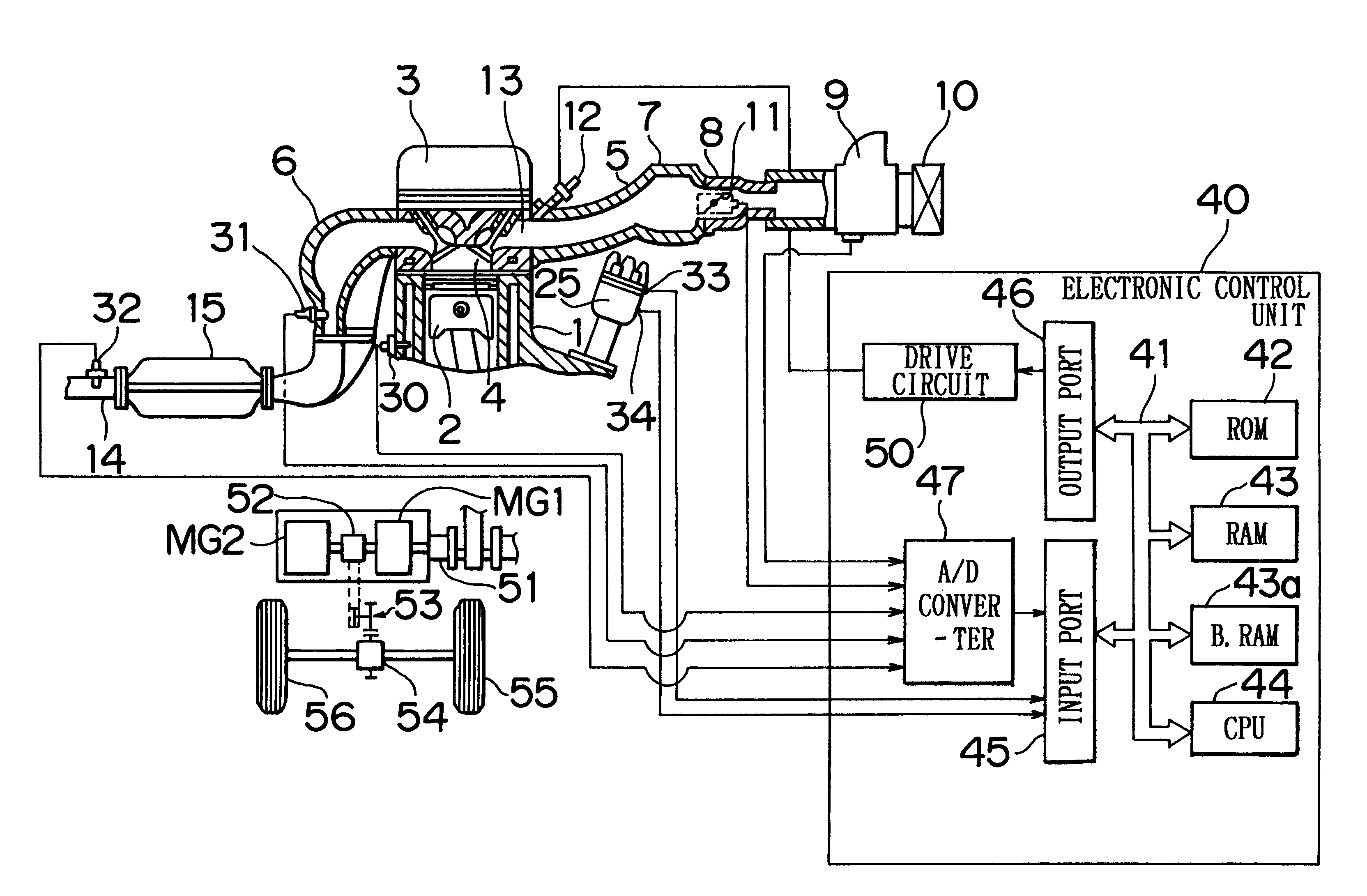
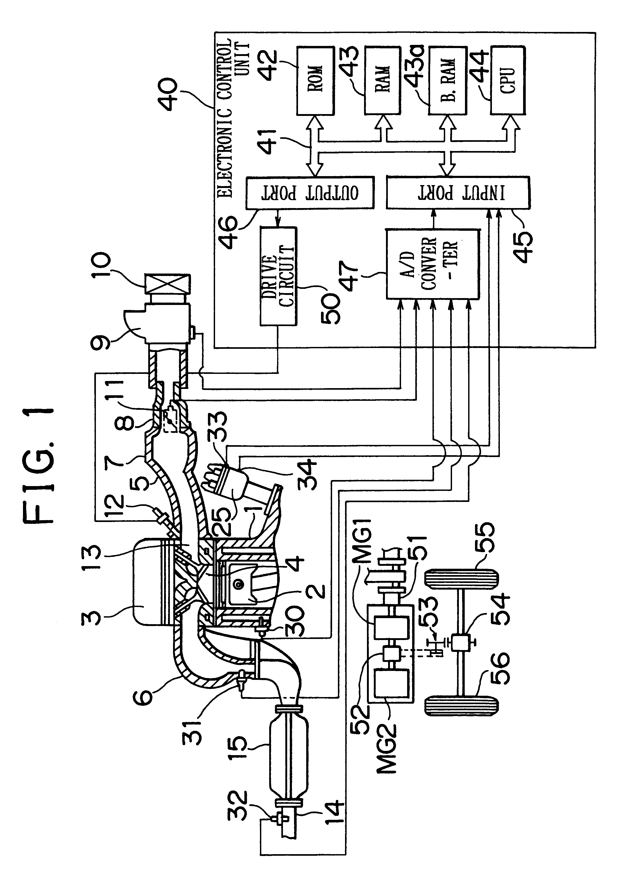
FIG. 1 illustrates an overall construction of the embodiment of the invention. An internal combustion engine has a cylinder block 1, pistons 2, a cylinder head 3, combustion chambers 4, an intake manifold 5, and an exhaust manifold 6. The intake manifold 5 is connected to an air cleaner 10 via a surge tank 7, an intake duct 8, and an air flow meter 9. A throttle valve 11 is disposed in the intake duct 8. Fuel injection valves 12 are disposed in the intake manifold 5 so as to inject fuel toward intake ports 13. The exhaust manifold 6 is connected to an exhaust pipe 14. Disposed in partway of the exhaust pipe 14 is a three-way catalytic converter 15 that simultaneously lessens three major fractions of exhaust gas, that is, hydrocarbons (HC), carbon monoxide (CO), and oxides of nitrogen (NOx).

An electronic control unit 40 is formed by a digital computer having a ROM 42, a RAM 43, a bac...


PUM


Abstract

A catalyst deterioration detecting apparatus for a hybrid vehicle having an internal combustion engine and an electric motor as power sources includes an air-fuel ratio sensor downstream of a catalyst disposed in an exhaust passage of the engine. An amount of oxygen stored in the catalyst is estimated and, based on the estimated amount of oxygen and an output produced by the air-fuel ratio sensor after the engine is restarted after having been temporarily stopped, it is determined whether the catalyst has excessively deteriorated.

Description

The disclosure of Japanese Patent Application No. HEI 10-374455 filed on Dec. 28, 1998 including the specification, drawings and abstract is incorporated herein by reference in its entirety.1. Field of the InventionThe present invention relates to a catalyst deterioration detecting apparatus for an internal combustion engine and, more particularly, to a catalyst deterioration detecting apparatus for an internal combustion engine provided in a hybrid vehicle employing both an internal combustion engine and an electric motor as power sources.2. Description of the Related ArtA three-way catalyst of a catalytic converter disposed in an exhaust passage of an internal combustion engine has an oxygen storage function taking up oxygen when the air-fuel ratio is on the fuel-lean side of a stoichiometric air-fuel ratio and, when the air-fuel ratio turns to a fuel-rich side of the stoichiometric air-fuel ratio, causing oxygen previously taken up during the fuel-lean state to react with hydroca...

Claims


Application Information

Patent Timeline
IPC IPC(8): B60K6/04B60K6/00F01N11/00F02B3/06F02B3/00B60K6/20F02D45/00B60K6/24B60K6/445B60W10/06B60W10/26B60W20/00F01N3/20F02D41/04F02D41/22
CPCB60K6/24B60K6/445B60W10/06B60W10/26F01N11/007B60L2240/445B60W2510/0619B60W2510/068B60W2710/0622F01N2550/02F01N2900/0422F02B3/06Y02T10/6295Y02T10/47Y10S903/903Y10S903/905Y02T10/6239Y02T10/62Y02T10/40
Inventor KUSADA, MASAKIHIROSE, KATSUHIKOKANAI, HIROSHITAKAOKA, TOSHIFUMIINOUE, TOSHIONISHIGAKI, TAKAHIROKOJIMA, MASAKIYO
Owner TOYOTA JIDOSHA KK
Learn More