Variable single-mode attenuators by spatial interference

a single-mode attenuator and spatial interference technology, applied in the field of variable attenuators, can solve the problems of false reading of optical signals, system error in detecting signals or inability to detect signals, and unreliable transmission of data

Inactive Publication Date: 2001-01-23
AGERE SYST INC
View PDF20 Cites 24 Cited by
  • Summary
  • Abstract
  • Description
  • Claims
  • Application Information

AI Technical Summary

Problems solved by technology

If a signal falls below the operational range, the system will either incorrectly detect the signal or will not detect the signal at all.
If the signal is above the operational range, the system will saturate and may result in a false reading of the data in the optical signal.
Thus, optical signal levels which are too high or too low result in unreliable transmission of data or can interfere with other data-carrying signals.
Further, the sensitivity of the receiver and the emitter output may exhibit changes due to aging.
A problem with this attenuation method is that the electromagnet dissipates large amounts of electrical power and is quite large.
In addition to being bulky, however, this method also is costly and slow-acting.
Such systems are temperature and polarization sensitive and organic material in the beam path can be chemically unstable, causing shortened device life.
Depending upon the cavity width and the wavelength of light used, the reflections will interfere constructively or destructively when they are received by an optical receiver (not shown).
Destructive interference refers to the effect caused by the receipt at the light collector of the two reflected signals in an "out of sync" state, which results in a signal of lesser strength or power, i.e., an attenuated signal.
Further degradation in performance (e.g., high attenuation occurring at the minimum attenuation point) is likely to occur where there are membrane holes in the optical path, although the degradation is negligible.

Method used


Image

  • Variable single-mode attenuators by spatial interference
  • Variable single-mode attenuators by spatial interference
  • Variable single-mode attenuators by spatial interference

Examples


first embodiment

FIGS. 5-7 illustrate different views of an attenuator according to the present invention. Referring to FIGS. 5-6, the reflective portions are divided by including a "large hole" 170 in the membrane 154 after coating the membrane with a high reflectivity (HR) coating. The floor 152 of the cavity is also coated with an HR coating. Note that it is not necessary to coat the entire regions indicated but only the regions that are illuminated by the incident beam, namely the middle region of the membrane 154 and the cavity floor 152 that is visible through the large hole 170. The illuminated area 172 (shown as a dotted circle) of the attenuator includes two portions or regions: (1) the crescent shaped area 174 on the membrane 154, and (2) the portion of the cavity floor 152 illuminated by the beam through the large hole 170. In a preferred embodiment, emphasizing high attenuations, the reflections from these two portions are approximately equal.

FIG. 7 illustrates the light reflection paths...

second embodiment

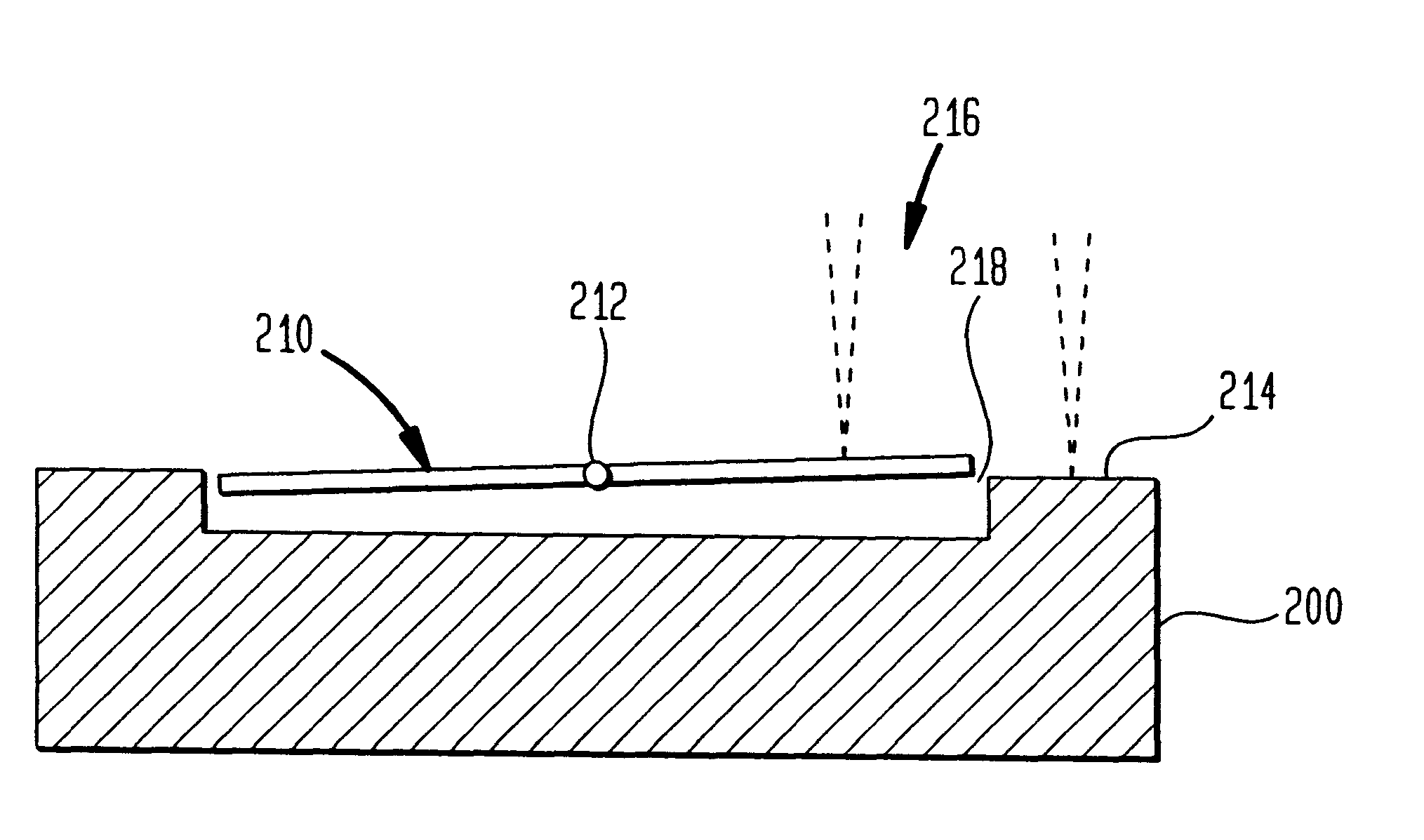
In a second embodiment, of the present invention reflective surfaces that are side-by-side are used in the attenuator as shown in, e.g., FIGS. 9 and 10, with one of the surfaces being moveable with respect to the other. Referring to FIGS. 9 and 10, the silicon chip 200 is seen from above and in cross-section, respectively. A moving surface 210, called a "see-saw" herein, pivots on torsion hinge mountings 212. As can be seen in FIG. 10, the right side of moving surface 210 is further away from the floor of the silicon chip 200 than the left side thereof. Maximum reflective coupling occurs for a light beam directed at the silicon chip 200 when the see-saw's top right edge is even with the top of the neighboring surface 214 of the chip 200; then the reflecting surface will appear to be an ordinary HR plane with a slight gap 218 (vertical slit) in the middle of the illuminated area 216. To maximize this coupling, the width of gap 218 relative to the light beam's diameter should be minim...

third embodiment

The sensitivity and symmetry of the attenuator can be improved by using two neighboring see-saws 220 and 222 as shown in, e.g., FIGS. 11 and 12 illustrates an attenuator according to the present invention. By directing the light beam 216 to straddle both see-saws 220 and 222 as shown, and applying the same forces to each one, twice the phase shift can be achieved.

Another group of variations comes from exploiting the transparency of silicon in the region of the infrared used for the variable attenuator. If the silicon is transparent and one (optionally) applies an AR (Anti-Reflecting) coating to the underside of the silicon chip and elsewhere as needed, one can make a variable reflective coupling through the underside.

It is not necessary for any of the designs to have the edges of the HR coatings be coincident with the edges of the holes or of the see-saws; the edges can be lithographically defined instead so that there is less danger of edge curling. The edges formed in this manner ...


PUM


Abstract

An optical attenuator is disclosed that utilizes the concept of destructive and constructive interference to enhance the ability to attenuate the light signal sent between an optical transmitter and an optical receiver. Rather than completely blocking out a portion of the light signal or utilizing a membrane coated with a partially reflecting material, the present invention utilizes a very high reflectivity coating on divided surfaces, and controls the relative distances between each of the divided surfaces and the optical transmitter/receiver.

Description

1. Field of the InventionThe present invention relates to a variable attenuator for attenuating an optical signal transmitted between an optical signal source and an optical signal receiver. More specifically, the present invention relates to the reflection of a transmitted optical signal off of divided surfaces for variably attenuating the optical signal.2. Description of the Related ArtIn optical data communications, signals are typically transmitted from a signal source to a signal receiver over an optical fiber network. FIG. 1 illustrates the general concept of optical signal transmission between an optical signal source 5 and an optical signal receiver 10, using a high reflectivity (HR) coated surface 15. For the sake of simplicity the various light beams illustrated in the figures are all shown as arcs to help in distinguishing their direction of travel; this illustration should not be considered as indicating any particular characteristic of the light beams themselves.Suppose...

Claims


Application Information

Patent Timeline
Patent Type & Authority Patents(United States)
IPC IPC(8): G02B6/35G02B6/26
CPCG02B6/266G02B6/3512G02B6/357G02B6/3584G02B6/3594
Inventor BERGMANN, ERNEST E.FORD, JOSEPH E.WALKER, JAMES A.
Owner AGERE SYST INC
Why Eureka
Try Eureka