Developer bearing body electroless plated on blasted surface using spherical particles, production method therefor and developing apparatus using the same

a development apparatus and development bearing technology, applied in the direction of instruments, applications, roads, etc., can solve the problems of sleeve pitch-shaped uneven density, turbulent image, defective image,

Inactive Publication Date: 2001-01-23
CANON KK
View PDF28 Cites 28 Cited by
  • Summary
  • Abstract
  • Description
  • Claims
  • Application Information

AI Technical Summary

Problems solved by technology

When the a-Si drum is used as a photosensitive drum at high humidities, an electric discharge product (such as NOx) adhering to the surface of the photosensitive drum takes up moisture so that surface charge on the photosensitive drum which forms an electrostatic latent image after charging and exposure escapes in the vicinity through the electric discharge product to disturb the latent image, resulting in a turbulent image.
When it is the first copy after the standby and for example, a halftone image which ought to have uniform density is copied, a defective image occurs as sleeve pitch-shaped unevenness in the density.
Toner is imbedded in these sharp concave portions to easily cause the sleeve contamination.
For the reason, however, the carbon-coated sleeve was inferior to SUS in respect of life although it has high hardness.
In recent years, however, there has been the tendency to further reduce the toner particle diameter in order to improve the image quality, and it could be understood that the sleeve contamination is prone to occur more than before.
Of course, if fine powder in the toner is removed, it will be possible to reduce smaller toner, but smaller toner cannot be reduced to 0% in the manufacturing cost of the toner.
Also, even if the particle diameter of the toner is not reduced as described above, if toner having low electrification property (particularly, positive toner) is used, slight sleeve contamination easily causes inhibited electrification of toner, resulting in a problem of low density.
In contrast, in the case of a high-hardness SUS sleeve, highly uniform asperities could not be obtained on the surface by the blasting treatment, but there are many minute concave portions and holes such as cracks within each concave portion.
Such difference in surface property is difficult to appear in the numerical values obtained by calculating the average value for surface roughness such as Ra and Rz, and is also difficult to be reflected in the average thread interval Sm and the like.
For this reason, any blasted surface having highly-uniform asperities cannot be obtained in the SUS sleeve, and it seems that there might be many microscopic concave portions within the crater-shaped concave portions.
By keeping the blasting pressure low, it is possible to form a blasted surface having high uniformity even in the SUS sleeve, but in this case, Ra and Rz will be lowered, which is not desirable in view of the toner conveying ability.
The SUS sleeve subjected to the blasting treatment using the spherical particles is much more difficult to cause the sleeve contamination than the SUS sleeve (FIG. 14) subjected to the Alundum blasting treatment of the conventional example, but in consideration of the use of smaller particle diameter toner in recent years, the

Method used


Image

  • Developer bearing body electroless plated on blasted surface using spherical particles, production method therefor and developing apparatus using the same
  • Developer bearing body electroless plated on blasted surface using spherical particles, production method therefor and developing apparatus using the same
  • Developer bearing body electroless plated on blasted surface using spherical particles, production method therefor and developing apparatus using the same

Examples


second experimental example

In this experiment, by combining a developer unit with the same development sleeve as in the first experimental example incorporated therein with an analog copying apparatus of a negative electrification system in which an OPC drum, we studied a case where a development sleeve according to the present invention is applied to image formation in the negative electrification system.

A photosensitive drum 1 consists of an OPC drum as described above, and the gap between the photosensitive drum and the development sleeve was set to 250 .mu.m. The photosensitive drum was charged at the surface potential -700 V, a latent image was formed at surface potential (non-image portion) -150 V, and normal development was performed using positively-chargeable magnetic toner having an average particle diameter of 7 .mu.m previously described. To the development sleeve, development bias in which DC voltage of -550 V is superimposed on a square wave (symmetrical bias) of AC voltage having peak-to-peak v...

second embodiment

This embodiment is, in a digital copying apparatus shown in FIG. 9 which has been described in the First Embodiment, the same as in the First Embodiment in the image formation conditions and the like except for the use of a development sleeve subjected to electroless Cr plating.

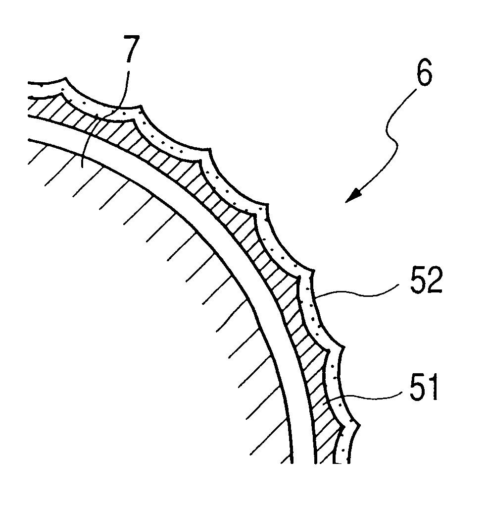
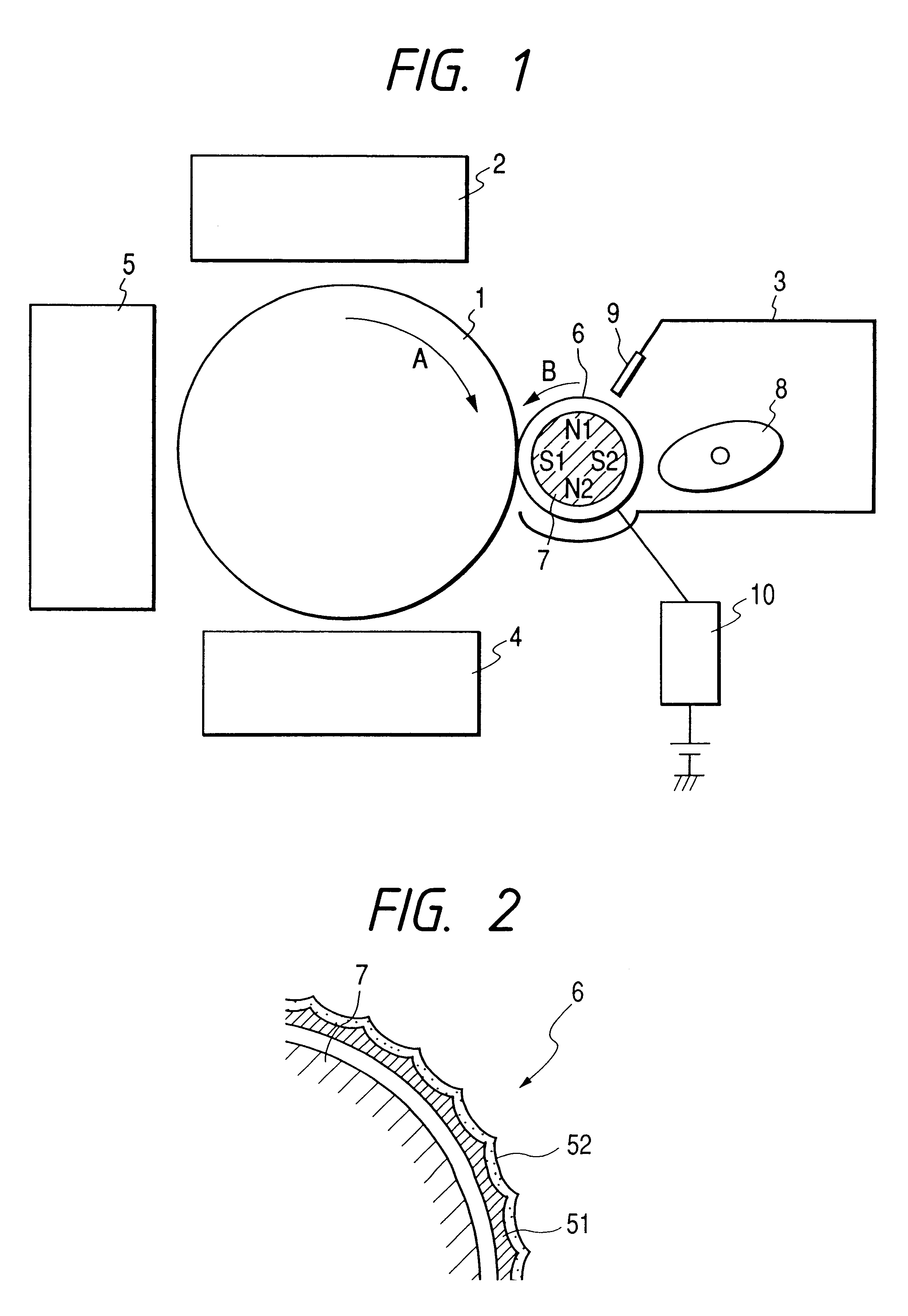
The development sleeve 6 is prepared by roughening the surface of an aluminum sleeve by the blasting treatment using spherical glass beads, and performing electroless Cr plating to cause it to have surface roughness Ra of 0.5 .mu.m, plating thickness of 5 .mu.m, and hardness Hv of about 600. The other structure of the developer device 3 is the same as the developer device 3 described in FIG. 1.

At this time, the amount of toner conveyance on the development sleeve was 0.8 mg / cm.sup.2 and the amount of toner charge was 13 .mu.C / g. In this case, while this embodiment is nearly the same in the amount of toner conveyance as in the First Embodiment, it is larger in the amount of toner charge than the First Embodime...

third embodiment

In this embodiment, as shown in FIG. 10, an elastic blade 9a was used instead of the magnetic blade as a developer regulating member in a developer device 3, and this elastic blade was caused to abut upon a development sleeve 6 directly. Also, for the development sleeve 6, a sleeve subjected to the electroless Cr plating described in the Second Embodiment was used.

The mechanical structure of an image forming apparatus itself according to this embodiment is basically the same as the First Embodiment of FIG. 1.

For a photosensitive drum 1, an OPC drum was employed, and the gap between the photosensitive drum and the development sleeve was set to 300 .mu.m. The surface of the photosensitive drum was charged at -600 V, a latent image was formed at surface potential -100 V by image exposure, and normal development was performed using negatively-chargeable magnetic toner. To the development sleeve, development bias in which DC voltage (-450 V) is superimposed on a square wave of AC voltage...


PUM

PropertyMeasurementUnit
Lengthaaaaaaaaaa
Lengthaaaaaaaaaa
Surface roughnessaaaaaaaaaa

Abstract

A method of fabricating a developer bearing body includes the steps of preparing metallic base material blasting the surface of the metallic base material using spherical particles and plating the surface of the metallic base material blasted, wherein a thickness of the plating layer is two or more times as large as a particle diameter in volume average of the developer.

Description

1. Field of the InventionThe present invention is used for image forming apparatuses such as copying machines and printers using the electrophotographic method and the electrostatic recording method, and relates to a developing apparatus for developing an electrostatic image on an image bearing body, a developer bearing body used for this developing apparatus and a production method for the developer bearing body.2. Related Background ArtConventionally, in an image forming apparatus of, for example, the electrophotographic type, an electrostatic latent image has been formed on an image bearing body made of electrophotographic photoreceptor, and the latent image has been developed by a developer unit. The developer unit has a development sleeve as a developer bearing body for bearing developer to convey.The surface of this development sleeve is unevenly roughened to promote the conveyance of developer, and there are known knurled grooves in a development sleeve mainly for two-compone...

Claims


Application Information

Patent Timeline
IPC IPC(8): G03G15/09G03G15/08
CPCG03G15/0928Y10T29/49544
Inventor MIZOGUCHI, YOSHITOHONDA, TAKAOSUZUKI, KAZUOHARA, NOBUAKI
Owner CANON KK
Why Eureka
Try Eureka