Vehicle cabin cooling system for capturing and exhausting heated boundary layer air from inner surfaces of solar heated windows

a technology of solar energy and cooling system, which is applied in the direction of vessel parts, vehicle cleaning, vessel construction, etc., can solve the problems of high peak cooling load that must be met by vehicle air conditioning system, increase the heat build-up, and increase the discomfort of passengers, so as to reduce heat build-up, uniform pressure drop, and the effect of heavy tinting

a technology of solar energy and cooling system, which is applied in the direction of vessel parts, vehicle cleaning, vessel construction, etc., can solve the problems of high peak cooling load that must be met by vehicle air conditioning system, increase the heat build-up, and increase the discomfort of passengers, so as to reduce heat build-up, uniform pressure drop, and the effect of heavy tinting

US6186886B1Inactive Publication Date: 2001-02-13ALLIANCE FOR SUSTAINABLE ENERGY

Image

  • Vehicle cabin cooling system for capturing and exhausting heated boundary layer air from inner surfaces of solar heated windows
  • Vehicle cabin cooling system for capturing and exhausting heated boundary layer air from inner surfaces of solar heated windows
  • Vehicle cabin cooling system for capturing and exhausting heated boundary layer air from inner surfaces of solar heated windows

Examples


Embodiment Construction

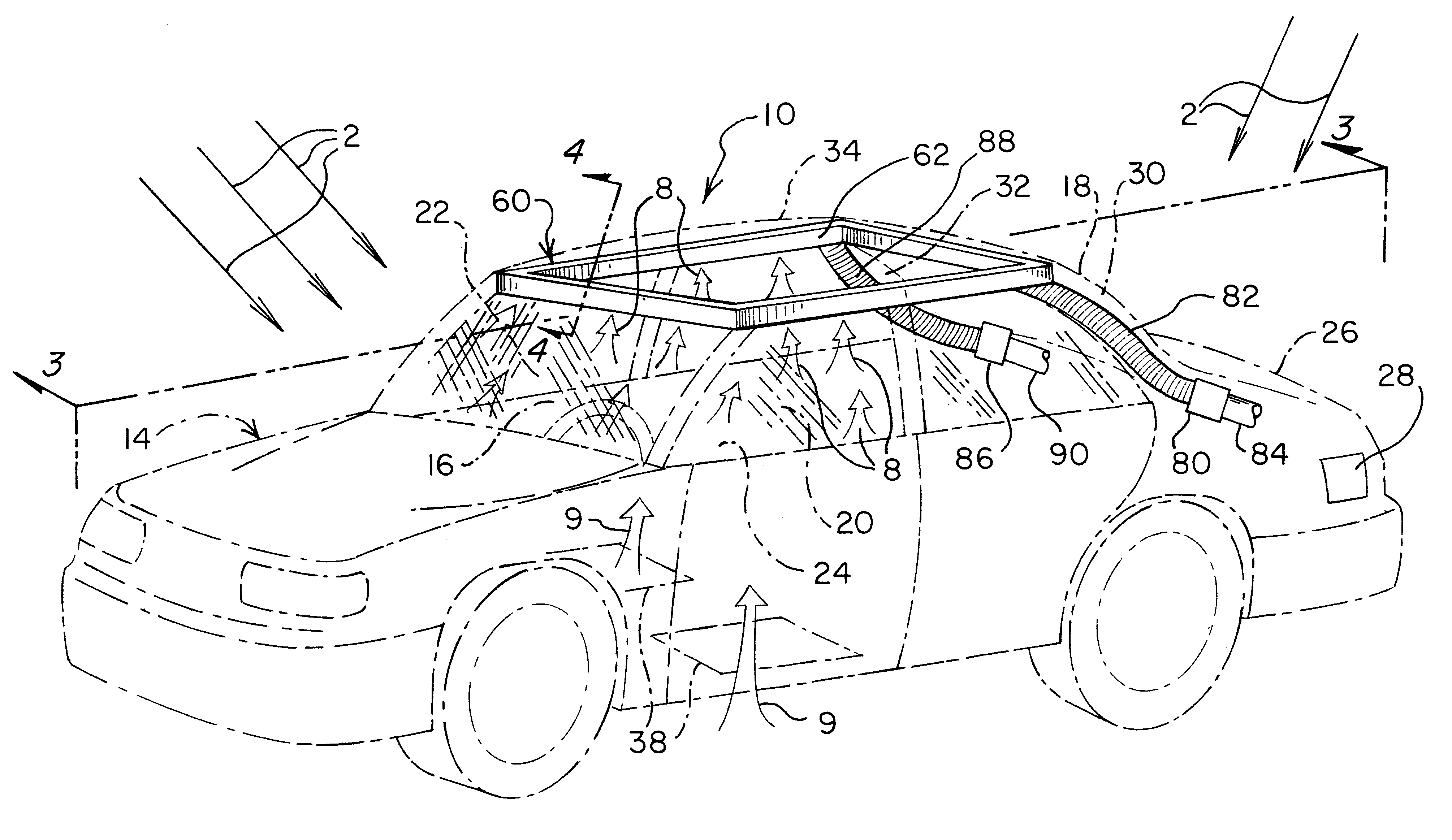
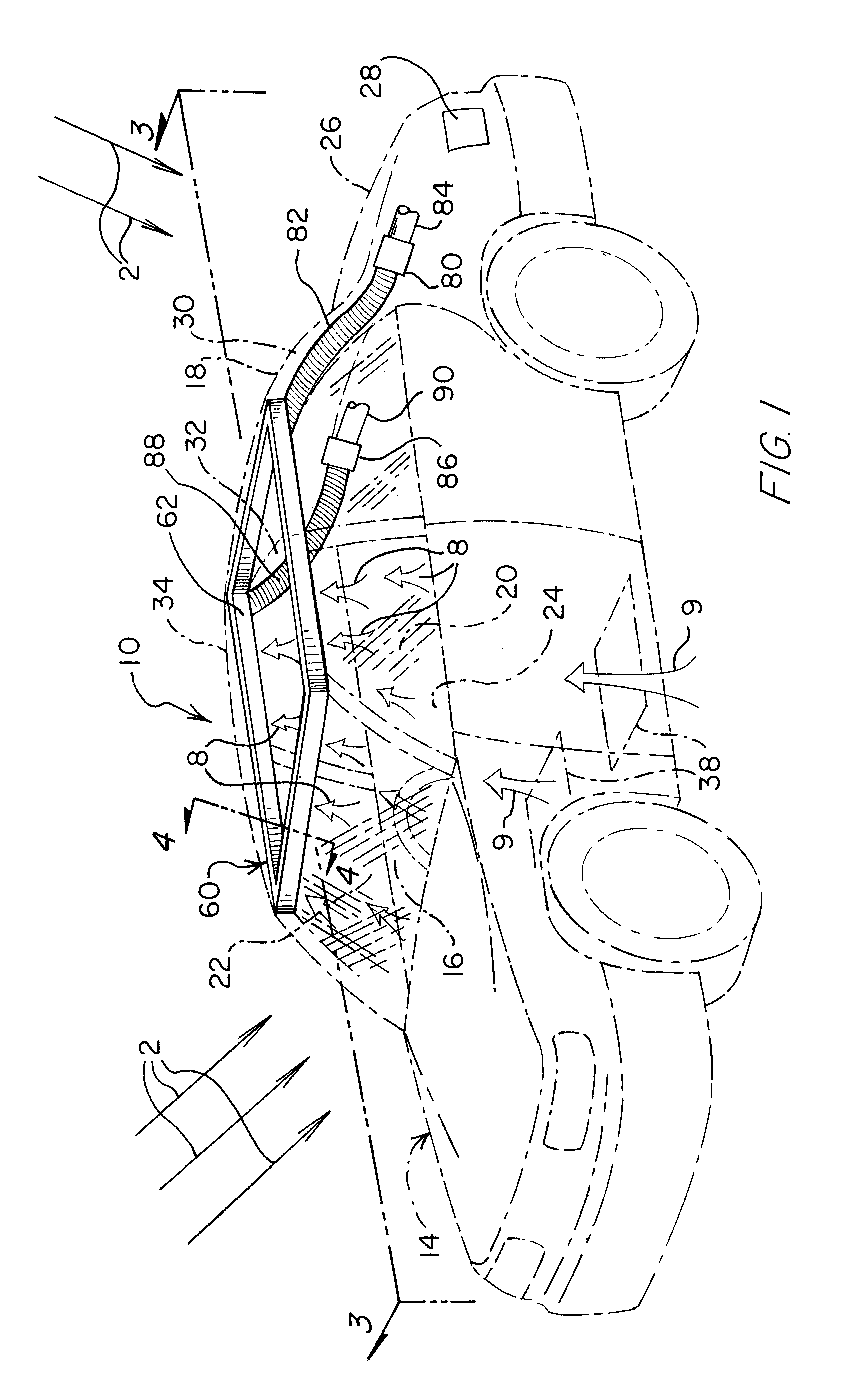
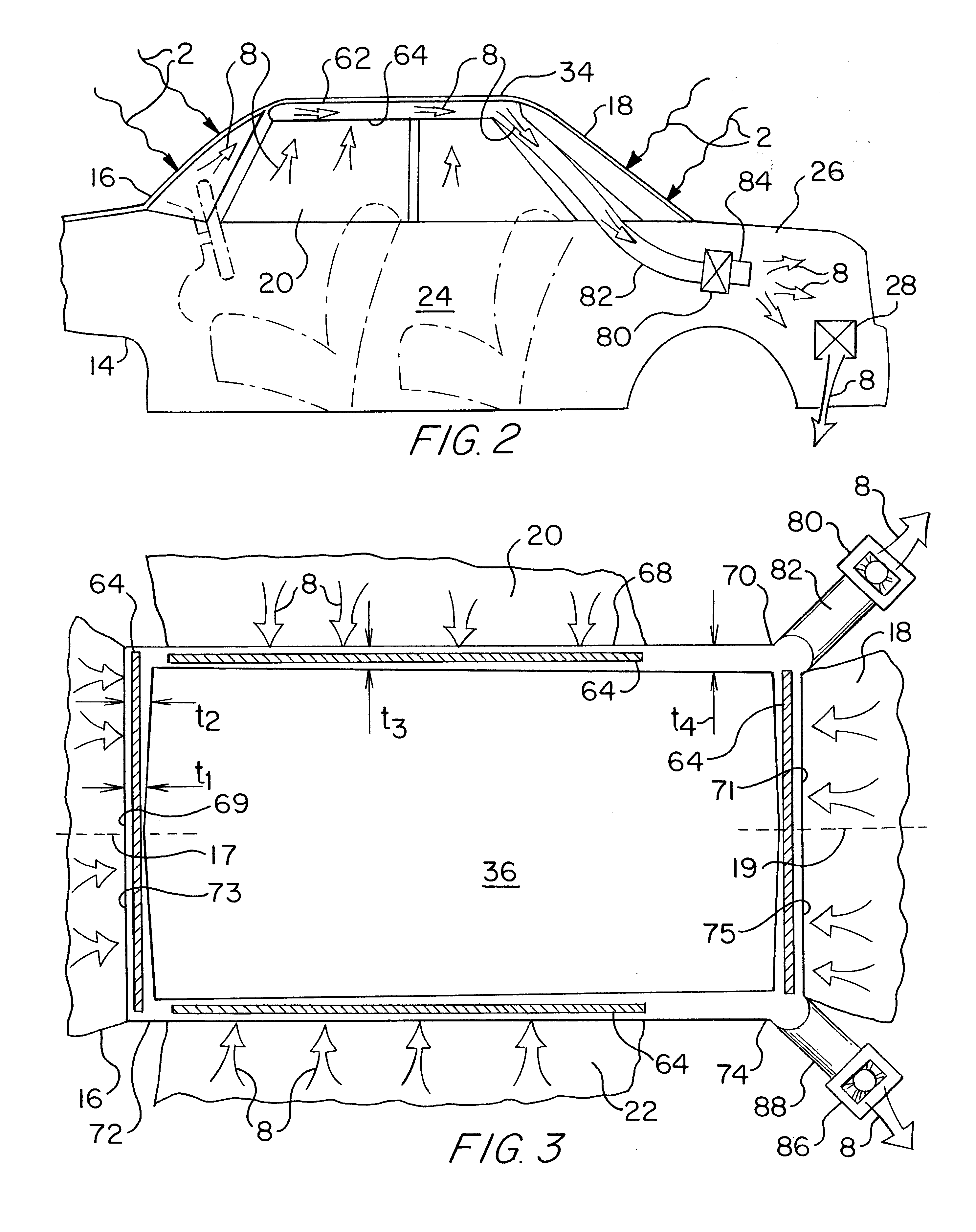
The cabin cooling system 10 of the present invention shown in FIGS. 1-5 includes boundary layer air capture and exhaust apparatus that selectively draws in air 8 flowing in thin, laminar-flow, boundary layers formed along solar-heated, interior surfaces of windshield 16 and other windows 18, 20, 22 of a vehicle 14. By selectively capturing the laminar flow boundary layers of heated air to the substantial exclusion of other air in the vehicle passenger cabin and discharging or exhausting that heated air 8 outside the passenger cabin, the cabin cooling system 10 effectively exhausts heat in absorbed in the air 8 and also inhibits transfer of heat by gas, i.e., air, conductance farther into the interior cabin of the vehicle 14.

Referring briefly to the windshield 16 cross-section of FIG. 4, some solar radiation 2 that is incident on the windshield 16 is transmitted 3 by the windshield 16 into the interior passenger cabin 24. Some of the incident solar radiation 2 is reflected 6 either b...


PUM


Abstract

The cabin cooling system includes a cooling duct positioned proximate and above upper edges of one or more windows of a vehicle to exhaust hot air as the air is heated by inner surfaces of the windows and forms thin boundary layers of heated air adjacent the heated windows. The cabin cooling system includes at least one fan to draw the hot air into the cooling duct at a flow rate that captures the hot air in the boundary layer without capturing a significant portion of the cooler cabin interior air and to discharge the hot air at a point outside the vehicle cabin, such as the vehicle trunk. In a preferred embodiment, the cooling duct has a cross-sectional area that gradually increases from a distal point to a proximal point to the fan inlet to develop a substantially uniform pressure drop along the length of the cooling duct. Correspondingly, this cross-sectional configuration develops a uniform suction pressure and uniform flow rate at the upper edge of the window to capture the hot air in the boundary layer adjacent each window.

Description

BACKGROUND OF THE INVENTION1. Field of the InventionThe present invention relates generally to a cooling system for a passenger compartment or cabin of a vehicle and more particularly to a cabin cooling system that captures and exhausts boundary layers of hot air that form on interior surfaces of vehicle windows that absorb energy and become hot from incident solar radiation.2. Description of Related ArtAn ongoing concern for the transportation industry is heat build-up within passenger compartments, i.e., cabins, of vehicles parked in the sun for long periods of time. The term "vehicles" includes, but is not limited to, automobiles (i.e., passenger vehicles), light duty vehicles such as sport utility vehicles (SUVs), trucks, and minivans, and miscellaneous other vehicles such as buses, larger trucks, tractors, trains, airplanes, and the like. Heat build-up leads to interior air temperatures up to 160.degree. F. and surface temperatures up to 250.degree. F. (i.e., "soak temperatures...

Claims


Application Information

Patent Timeline
13 Feb 2001
Publication
US6186886B1
IPC
B60H1/24
CPC
B60H1/243; B60H1/248
Inventors
FARRINGTON, ROBERT B.; ANDERSON, REN