
Method and system for continuously monitoring cardiac output

Inactive Publication Date: 2001-02-13
UNIVERSITY OF SOUTH CAROLINA
View PDF9 Cites 57 Cited by
  • Summary
  • Abstract
  • Description
  • Claims
  • Application Information

AI Technical Summary

Benefits of technology

In addition, because the system is relatively small and light weight, it may be easily moved to the patient or transported along with the patient (i.e., during an ambulance transfer).

Problems solved by technology

One technique known as the "direct method" is the most accurate but is largely restricted to the research laboratory because of the massively invasive or traumatic procedures which must be employed.
However, the transient indicator dilution procedure requires a specially trained physician to thread an expensive catheter through the right side of the heart and into the pulmonary artery.
During long term monitoring, infection at the site of catheter insertion and damage to the blood vessels of the lung are constant hazards.
The first two non-invasive methods are not readily utilized because the special equipment needed is extremely large and inconvenient to use.
In addition, with impedance plethysmography, accuracy is difficult to obtain and thus, it is a less favored method.
These methods require large, expensive equipment, and measurements are time consuming and require the efforts of several highly trained specialists to obtain and interpret results.

Method used


Image

  • Method and system for continuously monitoring cardiac output
  • Method and system for continuously monitoring cardiac output

Examples


Embodiment Construction

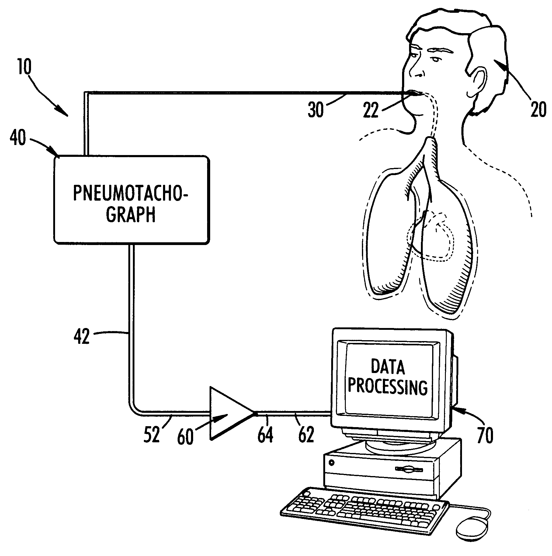
The present invention is a method and apparatus for measuring heart output, which is the amount of blood pumped by a heart in a given period of time. The measurement, rather than being a direct measurement of blood flow from the heart, is of air flow in the throat based on the theory that the beating heart influences that air flow by pressing on the lungs.

The heart lies inside the airtight chest and is surrounded by the lungs. The heart is filled with blood, an incompressible fluid. When the left side of the heart beats, it ejects a certain quantity of blood which is called stroke volume (SV). Most of the SV leaving the left ventricle of the heart leaves the chest through the aorta. At a heart rate of 77 beats / min, SV in the average healthy adult is approximately 65 ml. The sudden ejection of blood from the closed chest decreases the total volume of the chest cavity.

The chest wall is compliant thus it will expand or contract when the pressure exerted by, or the volume of, its conten...


PUM


Abstract

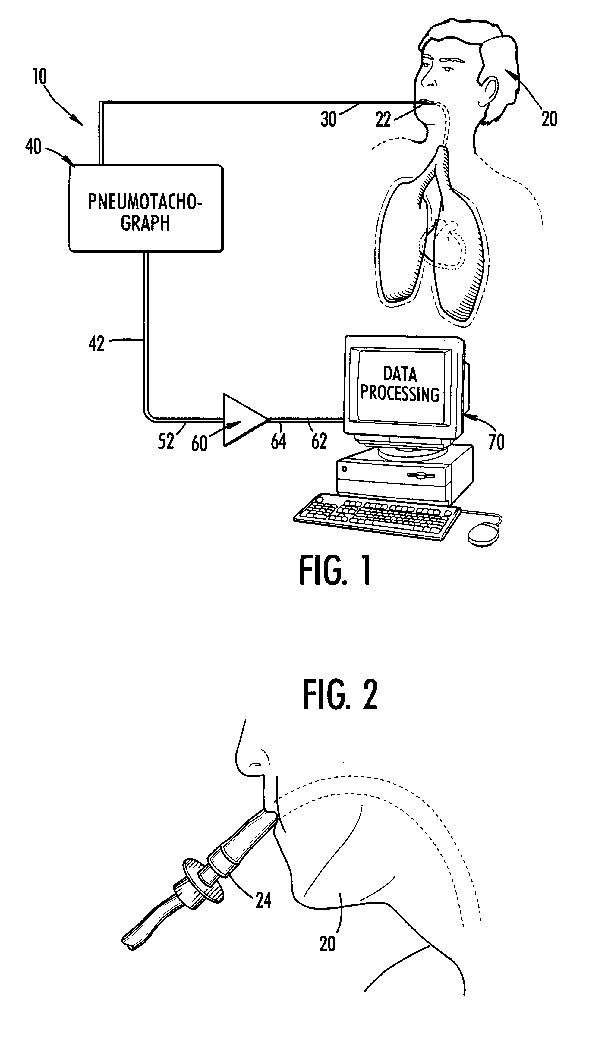
The present invention is a method and system for continuously monitoring cardiac output. In a preferred embodiment, the method and system of the present invention comprises a pneumotachograph, differential pressure transducer, and a signal amplifier / conditioner interconnected to a programmed digital computer. A patient, preferably, inserts the pneumotachograph in his mouth or, alternatively, the pneumotachograph is connected to a patient's tracheal cannula. As the patient exhales and inhales the differential pressure transducer measures the drop in pressure as air flows through the pneumotachograph thereby producing a weak electrical signal non-linearly proportional to flow. Next, the weak signal is directed through the amplifier / signal conditioner which increases the amplitude and removes some of the noise contained in the transducer output. A digital computer is then utilized to convert the analog time varying electrical signal into a stream of digital data, store it on disk, display it in real time and processes the signal using an experimentally determined correlation factor and mathematical equations relating the fluctuations in air flow with stroke volume to obtain the cardiac output.

Description

1. Field of the InventionThe present invention relates to a method and system for monitoring cardiac output. In particular, the present invention relates to a method and system for continuously monitoring cardiac output without injection or withdrawal of liquids into the patient.2. Discussion of BackgroundAccurately measuring and monitoring cardiac output has long been a clinical and research goal. Both direct and indirect methods are known. Because the history of cardiac monitoring goes back to the early part of this century, there have been many techniques devised. A representative rather than an exhaustive list has been prepared to summarize the methods employed.One technique known as the "direct method" is the most accurate but is largely restricted to the research laboratory because of the massively invasive or traumatic procedures which must be employed. Less destructive, indirect methods include steady-state Fick oxygen uptake, the transient indicator dilution method, and ane...

Claims


Application Information

Patent Timeline
IPC IPC(8): A61B5/08A61B5/083A61B5/026A61B5/029
CPCA61B5/083A61B5/029
Inventor MCNAMEE, JAMES E
Owner UNIVERSITY OF SOUTH CAROLINA
Learn More