Hydraulically actuated cutoff valve and hydraulic brake system for a vehicle

a technology of hydraulic brake system and cutoff valve, which is applied in the direction of braking system, braking components, operating means/release devices of valves, etc., can solve the problems of variable switching pressure and high cost of valves

Inactive Publication Date: 2001-02-20
ROBERT BOSCH GMBH
View PDF5 Cites 6 Cited by
  • Summary
  • Abstract
  • Description
  • Claims
  • Application Information

AI Technical Summary

Problems solved by technology

The known valve has the disadvantage of being expensive to produce.
Using two springs operating contrary to one another presents a high risk that the switching pressures will vary over the course of valve use.

Method used


Image

  • Hydraulically actuated cutoff valve and hydraulic brake system for a vehicle
  • Hydraulically actuated cutoff valve and hydraulic brake system for a vehicle
  • Hydraulically actuated cutoff valve and hydraulic brake system for a vehicle

Examples


Embodiment Construction

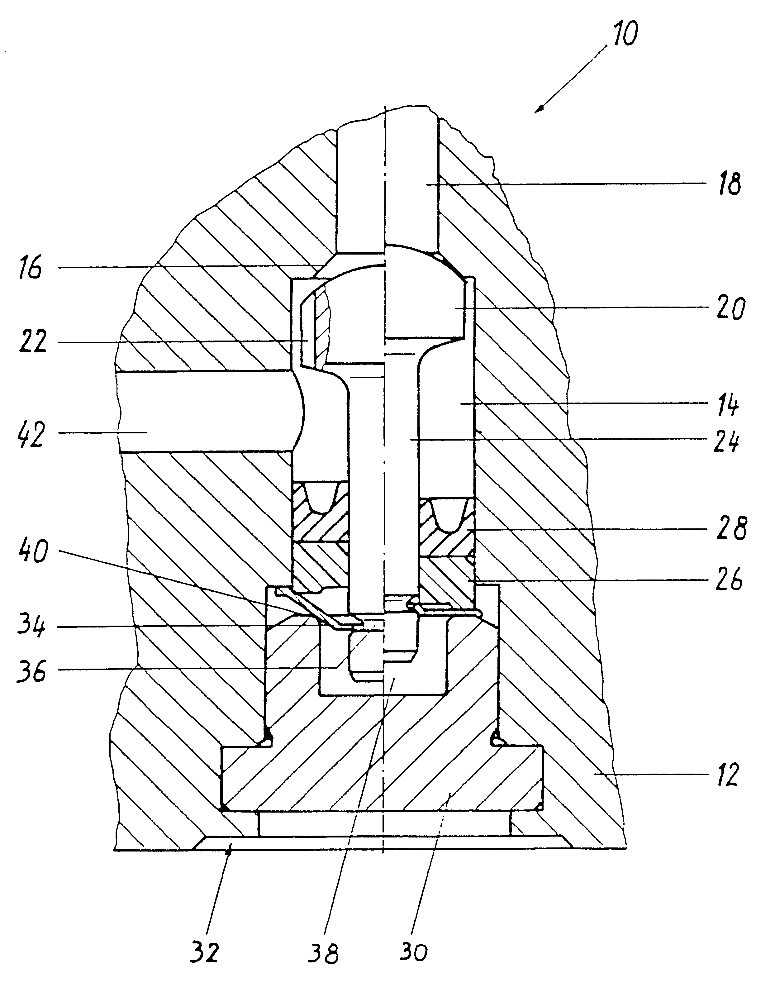
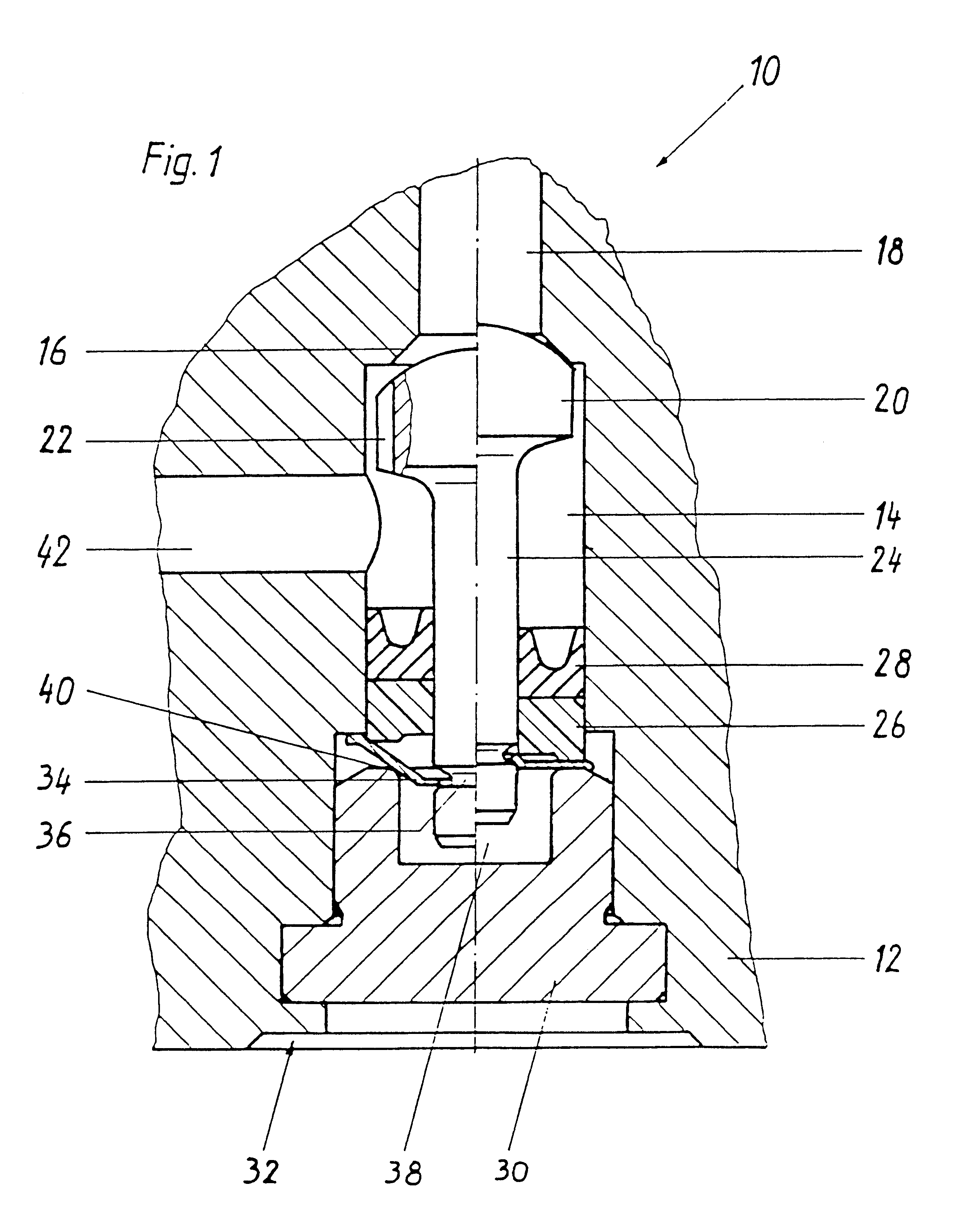
The hydraulically actuated cutoff valve of the invention shown in FIG. 1 and identified overall by reference numeral 10 is a 2 / 2-way valve. It is inserted into a hydraulic block, of which the drawing shows only a fragment containing the cutoff valve 10. Via the hydraulic block, the cutoff valve 10 communicates hydraulically with other components of a vehicle brake system, such as magnet valves, a master cylinder, and / or a pump. The hydraulic block forms a valve housing 12 and will hereinafter be called by that name.

The valve housing 12 has a cylindrical bore, which forms a valve chamber 14. On one end of the valve chamber 14, an annular shoulder is made with a conical valve seat 16 at which an axial fluid conduit 18 discharges.

A spherical valve closing body 20 is axially displaceably supported in the valve chamber 14 and is shown in the drawing in two halves, one in a closed position and one in an open position. This body has lengthwise ribs 22 on its circumference. The lengthwise r...


PUM


Abstract

The invention relates to a hydraulically actuated cutoff valve which is provided as an intake valve for switching between a master cylinder and an intake side of a feed pump of a slip-controlled vehicle brake system. The invention sets forth that the cutoff valve is embodied with a valve closing body that has a valve tappet which passes through an annular actuating element and is in engagement with a rocker element embodied as a cup spring, which rests on an annular pivot bearing. If the actuating element is acted upon by pressure, it presses down an outer edge of the rocker element, and as a result a middle of the actuating element executes a pivoting motion in the opposite direction that closes the cutoff valve. The invention has the advantage of an economical cutoff valve that has only a small number of components, and the invention can be used in a hydraulic vehicle brake system.

Description

PRIOR ARTThe invention relates to a hydraulically actuated cutoff valve and a hydraulic brake system for a vehicle, which can be equipped with such a cutoff valve.One such valve is known from European Patent Disclosure EP 0 606 840 B1. The known valve has a valve housing with a partition on which a valve seat is formed. Disposed on one side of the partition is a piston as an actuating element, which is pressed by a valve opening spring in the direction of the partition and can be displaced away from the partition by imposition of pressure. Located on the other side of the partition is a valve ball acting as a valve closing body, which is lifted from the valve seat by the piston and is pressed in the direction of the valve seat by a valve closing spring which is weaker than the valve opening spring. The known valve is open in its basic position and is closed by imposition of a pressure that is above a closing pressure.The known valve has the disadvantage of being expensive to produce...

Claims


Application Information

Patent Timeline
Patent Type & Authority Patents(United States)
IPC IPC(8): B60T8/34B60T8/36F16K31/56F16K31/44
CPCB60T8/341B60T8/4872Y10T137/7835
Inventor ALAZE, NORBERTSIEGEL, HEINZHUMMEL, ROLFMICHL, THOMASMAIER, MARTINHOHL, GUENTHER
Owner ROBERT BOSCH GMBH
Why Eureka
Try Eureka