Electric dust collecting apparatus and manufacturing method of the same

a technology of dust collecting apparatus and manufacturing method, which is applied in the direction of electrostatic separation, chemistry apparatus and processes, solid separation, etc., can solve the problems of poor workability and productivity, poor use effect, and poor use effect of equipment and machinery, so as to improve the production rate of needle electrodes and improve the effect of remarkable strength and good workability

Inactive Publication Date: 2001-02-27
O DEN CORP TOKIO TOKYO
View PDF21 Cites 24 Cited by
  • Summary
  • Abstract
  • Description
  • Claims
  • Application Information

AI Technical Summary

Benefits of technology

As described the construction above, the plurality of deflection electrodes can be integrally formed from a profile punched up from a sheet metal by the punching and bending press process, enabling the manufacturing process to have good workability and productivity.
The needle electrode can be fixed to the front plate potion of deflection electrodes by not only brazing but also by caulking and impact work, enhancing production rate of the needle electrode fabricated on the deflection electrode, in addition, the needle electrode can be inserted into the needle electrode mounting hole, causing good coupling between them to increase remarkable strength, also enhancing impact resistance against the mechanical and thermal interference. Consequently, low production cost and mass-production can be achieved.

Problems solved by technology

Therefore, air stagnates in the buildings.
Such air contains smoke floating in the air caused by tobacco, toner come out from a copy machine, particles of copy papers dust together with bad smell and often toxic substance therein.
This impairs people in the buildings in health, and also makes the facilities and machines dirty.
However, since the dust collector 2 has 50 to 200 pieces of the needle deflection coupled electrodes 10, much time and labor are required to produce the needle deflection coupled electrodes 10 with the use of the silver solder G. Consequently, the air cleaner is high in manufacturing cost and low in productivity.
In addition, the needle electrode 15 is connected with the abutting portion of the front plate portion through a butt joint, which is unstable in operation to offer a disadvantage.

Method used


Image

  • Electric dust collecting apparatus and manufacturing method of the same
  • Electric dust collecting apparatus and manufacturing method of the same
  • Electric dust collecting apparatus and manufacturing method of the same

Examples


first embodiment

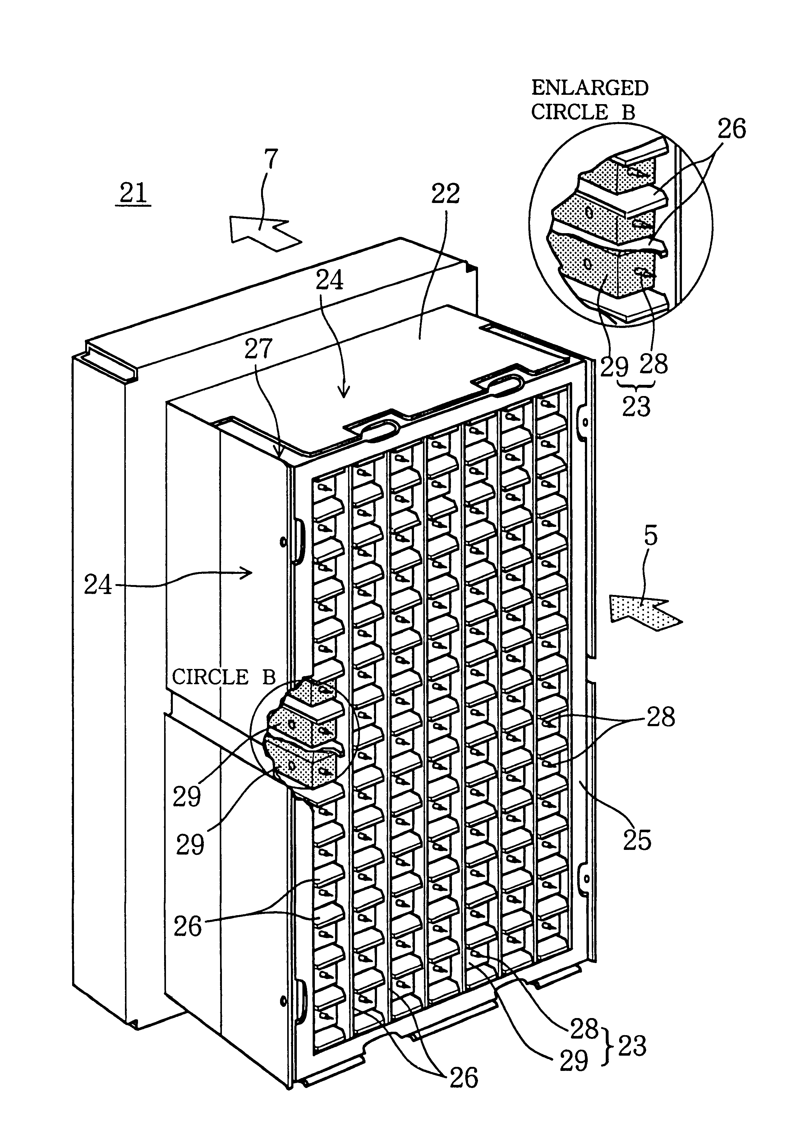
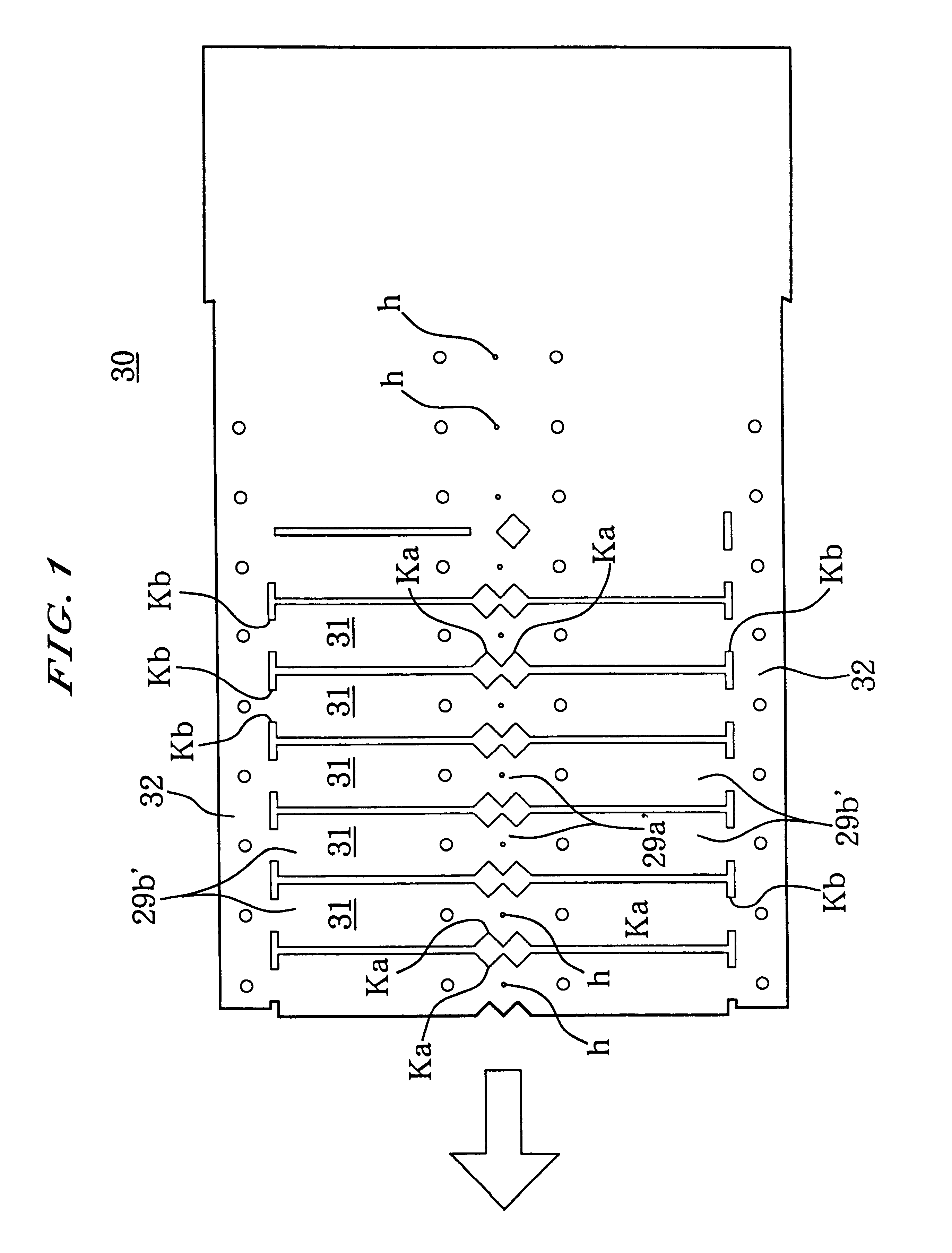
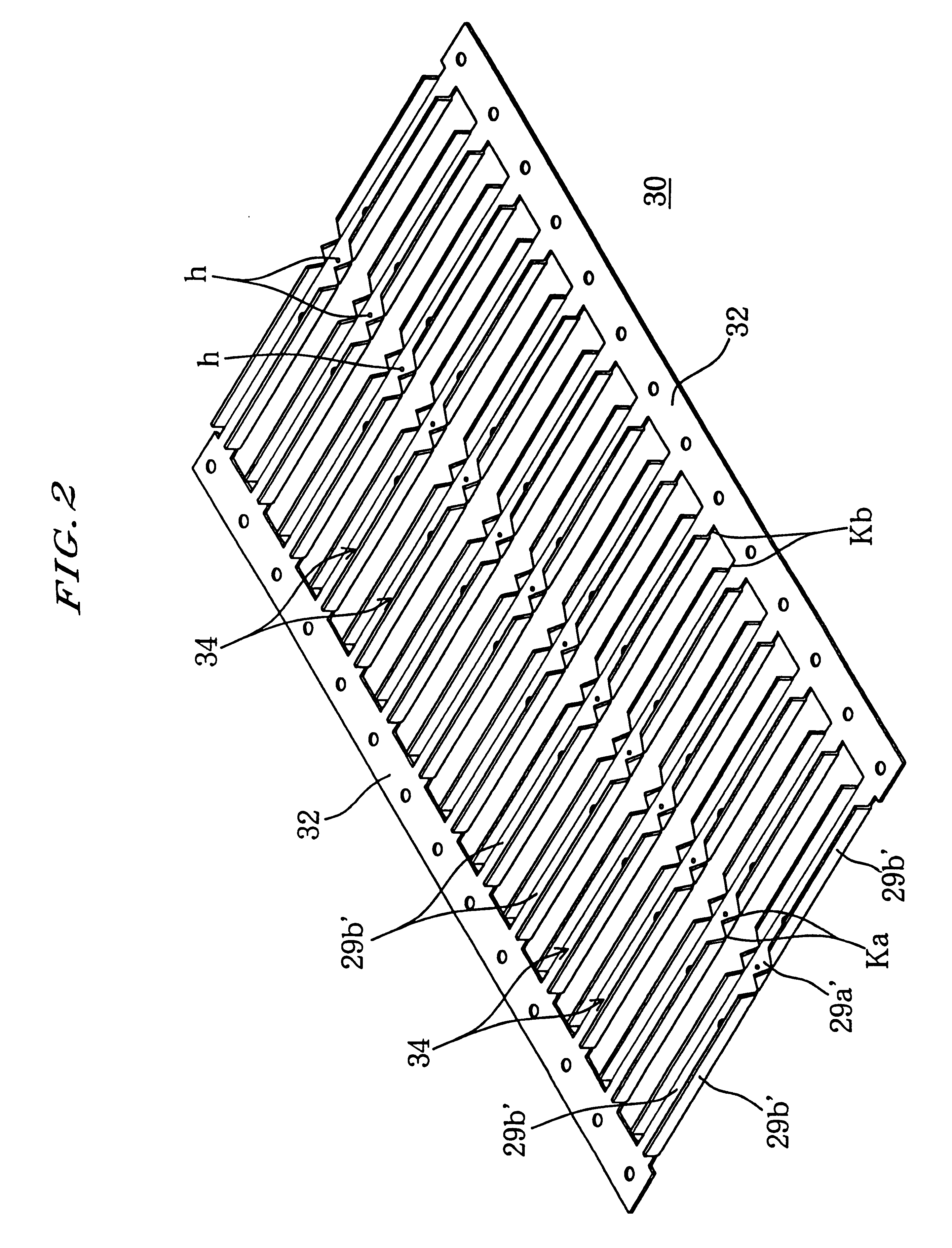
FIGS. 1 to 4, 5(a) to 5(c) and 6 to 9 are explanatory views of a method of manufacturing major part of an air cleaner in a first embodiment of the present invention, concretely, of manufacturing a number of needle deflection coupled electrodes integratedly fabricated in series, in which FIG. 1 is a plan view of a profile portion punched up a sheet metal and indicating a two-dimensional shape of needle deflection coupled electrodes; FIG. 2 is a perspective view showing a middle processed product bent the profile portion by a punch press; FIGS. 3 and 4 are perspective views showing a middle processed product of inserting needle electrodes; FIGS. 5(a) to 5(c) are perspective views and their sectional views showing steps of fabricating the needle electrode; FIG. 6 is a perspective view showing the needle deflection coupled electrodes having the needle electrodes; FIGS. 7 to 9 are perspective views showing the fabricating order of a male-type sub-unit having a number of needle deflection...

second embodiment

The second embodiment is different from the first embodiment in that the needle electrode 45 is fixed to the deflection electrode 29 by a caulking manner instead of by the impact and that the needle electrode 45 has a needle portion 45a, a relatively thick portion 45b and a relatively thin portion 45c instead of having the needle portion and body portion. Detailed descriptions of manufacturing those are omitted since the mostly same method in the first embodiment is involved in the second embodiment, therefore, the same reference numerals are designated on FIGS. 17(a) to 17(c) as used on FIGS. 5(a) to 5(c).

The method of mounting the needle electrode 45 on the deflection electrode 29 will now be described with reference to FIGS. 17(a) to 17(c).

In order of fixing the needle electrode 45 to the middle processed portions 3434, . . . (referring to FIG. 2) as shown in FIG. 17(a), the relatively thin portion 45c of needle electrode 45 is inserted into the mounting hole h, edge portion of w...

third embodiment

The third embodiment different from the second embodiment is that the needle electrode 45 is fixed with the brazing work instead of the caulking work, as shown in FIGS. 18(a) to 18(c).

Detailed descriptions of the step in manufacturing are omitted since the mostly same method in the second embodiment is involved in this embodiment. Therefore, the same reference numerals are designated on FIGS. 18(a) to 18(c) as those used on FIGS. 17(a) to 17(c).

The needle electrode 45 is fixed lo the front plate 29a' by the brazing work, enhancing uniformity of the junction quality and stabilization of dust collection. The needle electrode 45 is fixed to the middle processed portion 34, but may be fixed to a complete unit shown in FIGS. 6 to 9, for example.

Fourth Embodiment

A fourth embodiment of the present invention will be described next. FIG. 19 is a perspective view showing a male-type subunit body 48.


PUM

PropertyMeasurementUnit
thickaaaaaaaaaa
lengthaaaaaaaaaa
voltageaaaaaaaaaa

Abstract

An electric dust collecting apparatus includes at least one needle electrode for charging floating particles in air by generating a corona discharge around needle points; at least one collecting electrode provided on cell-liked arrangement corresponding to the needle electrodes, for attracting and collecting the charged floating particles by an electrostatic force; and at least one deflection electrode having a rectangularly hollow longitudinal structure having a front plate portion and side plate portions wherein the needle electrodes are fixed on the front plate portion, for applying a deflection force to the charged floating particles to move toward the collecting electrodes by a potential applied from the side plate portions, and wherein the at least one deflection electrode having the rectangularly hollow longitudinal structure is obtained by bending a profile plate punched up a sheet metal by a predetermined punch press process, accordingly, the plurality of deflection electrodes can be integratedly formed from a profile punched up from a sheet metal by the punching and bending press process, enabling the manufacturing process to have workability and productivity.

Description

FIELD OF THE INVENTIONThe present invention relates to an electric dust collecting apparatus and a manufacturing method of the same, and more particularly to an electric dust collecting apparatus and a manufacturing method of the same suitably used for such as an air cleaner, a black smoke removing apparatus for Diesel engine's exhaust and an oil-mist removing apparatus for use in a factory.DISCUSSION OF THE BACKGROUNDRecently, buildings such as office buildings, restaurants, recreation facilities, factories, housings have substantially air-tight structures. Therefore, air stagnates in the buildings. Such air contains smoke floating in the air caused by tobacco, toner come out from a copy machine, particles of copy papers dust together with bad smell and often toxic substance therein. This impairs people in the buildings in health, and also makes the facilities and machines dirty. Due to this, the use of an electric dust collecting-type air cleaner has spread. Such cleaner is instal...

Claims


Application Information

Patent Timeline
Patent Type & Authority Patents(United States)
IPC IPC(8): B03C3/40B03C3/41
CPCB03C3/40B03C3/41Y10T29/49604Y10T29/5116B03C2201/10
Inventor NOJIMA, KOUZABUROU
Owner O DEN CORP TOKIO TOKYO
Why Eureka
Try Eureka