Electrostatic lens

Inactive Publication Date: 2001-02-27
IMS IONEN MIKROFABATIONS SYST
View PDF2 Cites 16 Cited by
  • Summary
  • Abstract
  • Description
  • Claims
  • Application Information

AI Technical Summary

Problems solved by technology

The production of such a "perfect" system is implying considerable measures and costs.
Furthermore, in case of a defect or a change in shape or alignment of the electrodes, for example, due to environmental factors, the repair or realignment of the system is particularly difficult.
If, during the mounting of an ion beam lithography install

Method used


Image

  • Electrostatic lens
  • Electrostatic lens
  • Electrostatic lens

Examples


Example

)

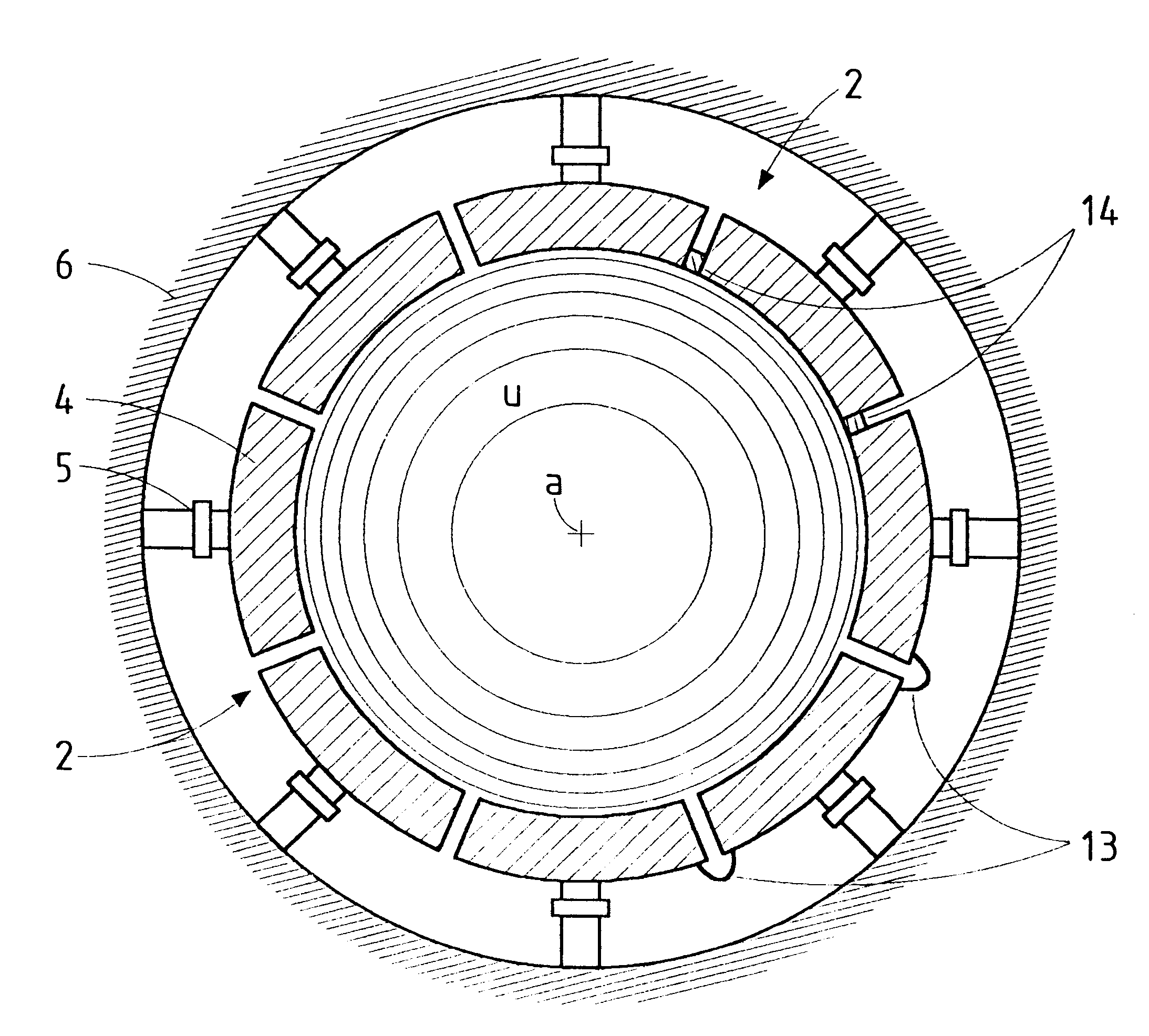
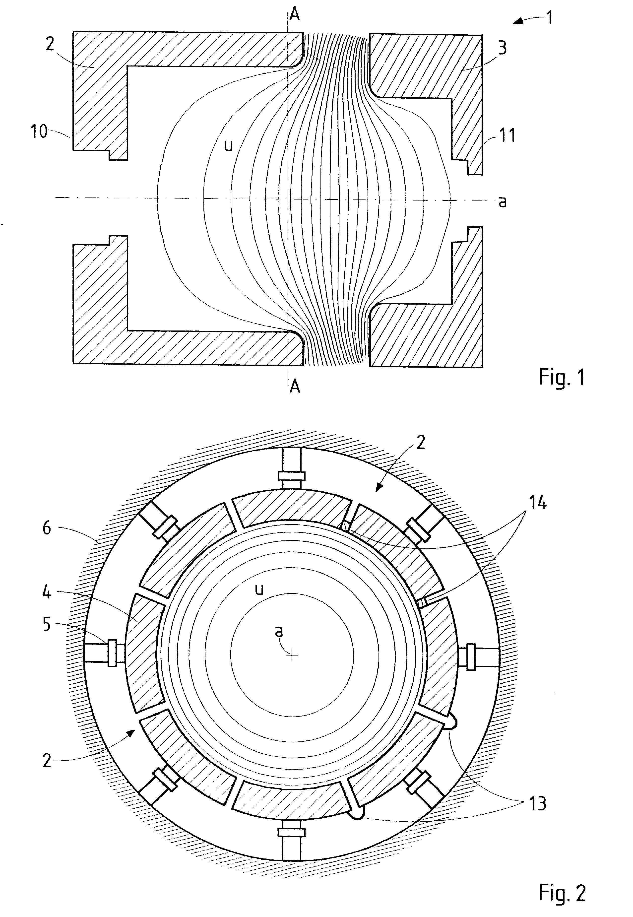
The electrostatic lens 1 shown in FIG. 1 is mechanically adjustable and consists of two lens electrodes 2, 3 made of an electric conductor, such as aluminum. The electrodes 2, 3 are held at on strong but differing potentials U1 and U2, respectively, and produce a potential distribution in the inner space of the electrostatic lens 1, said potential distribution being indicated in FIG. 1 with the help of the equipotential lines U.

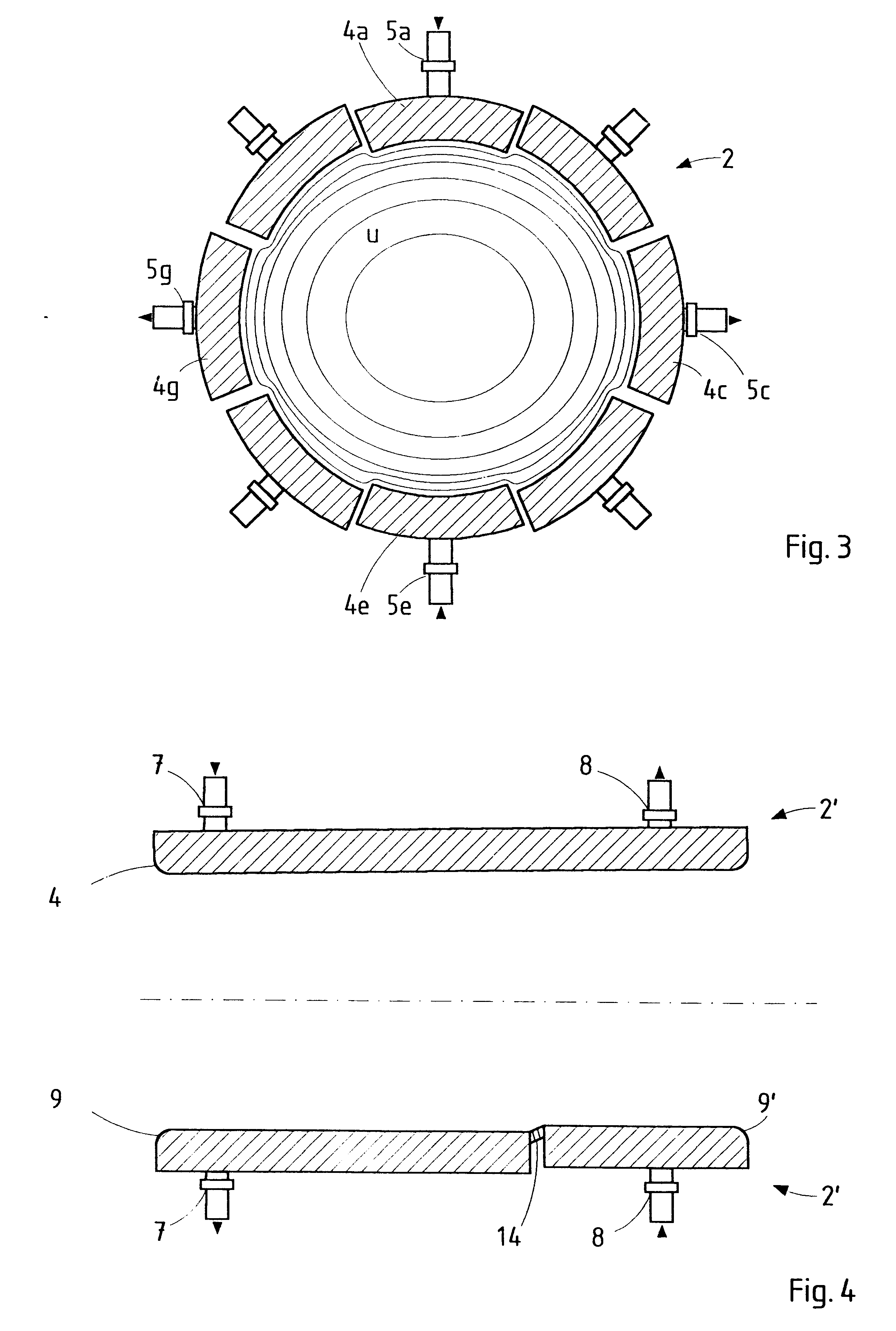
According to the present invention, at least one of the electrodes is divided into sector areas. In this case, it is the front electrode 2 shown in FIG. 2 which is divided into spaced apart sectors 4 and shows the cross-section through electrode 2 in the position shown in FIG. 1 by the line A--A. The basic shape of electrode 2 is rotationally symmetrical around the longitudinal axis a, its cross- section being essentially ring-shaped with a circular inner edge, i.e. the inner surface is either cylindrical or conical according to their course in axial directi...


PUM


Abstract

Electrostatic lens for focussing the beams of charged particles, more particularly of ions, which have electrodes being designed as an electric conductor with a ring-shaped section, the inner edge of which is essentially circular, whereas at least one of the electrodes is composed of sector areas (4) succeeding one another along the periphery of an electrode, whereaseach sector area is covering one predetermined angle area of the periphery,the sector areas are electrically connected to one another andthe sector areas are linked to the holding device via at least one adjusting element per sector areathe position of the sector areas may be adjusted irrespective of the other sector areas by means of the adjusting elements during operation of the electrostatic lens.The sector areas may be mechanically separated or extend from one thickness minimum of an electrode cross-section with periodically varying thickness to the next one.

Description

1. Field of the InventionThe present invention relates to an electrostatic lens for focusing the beams of charged particles, more particularly of ions, which have at least two electrodes being designed as an electric conductor with a ring-shaped section, the inner edge of which is essentially circular, whereas each electrode is connected to a power supply, can be connected to an electric potential and is fastened on a holding device.2. Description of the Prior ArtElectrostatic lenses are used in particle optical systems and may be used for multi-various applications. Of particular interest is the application of ion beam lithography used in structure semiconductors. In the case of ion beam lithography, an ion beam pictures the structures of a shadow mask on a wafer in a usually reduced picture. In order to produce a well defined picture of the mask structures on the wafer with the help of the ion beam, the ion beam is led through an imaging system in which a number of electrodes held...

Claims


Application Information

Patent Timeline
IPC IPC(8): H01J37/10H01J37/12G21K1/087
CPCH01J37/12H01J2237/153H01J2237/31755
Inventor CHALUPKA, ALFREDSTENGL, GERHARD
Owner IMS IONEN MIKROFABATIONS SYST
Why Eureka
Try Eureka