Drive device for moving a sliding sunroof of a vehicle

a technology for driving devices and vehicles, which is applied in the direction of roofs, gearing, transportation and packaging, etc., can solve the problems of affecting the assembly of the drive device, the assembly method described not only requires some skill, and the failure to ensure the faultless operation of the drive devi

Inactive Publication Date: 2001-03-13
ROBERT BOSCH GMBH
View PDF3 Cites 100 Cited by
  • Summary
  • Abstract
  • Description
  • Claims
  • Application Information

AI Technical Summary

Problems solved by technology

An exact positioning of the brush holder or of the brushes resting against the commutator is necessary since otherwise, a faultless operation of the drive device cannot be assured.
The assembly method described not only requires some skill, but it also hinders ...

Method used


Image

  • Drive device for moving a sliding sunroof of a vehicle
  • Drive device for moving a sliding sunroof of a vehicle
  • Drive device for moving a sliding sunroof of a vehicle

Examples


Embodiment Construction

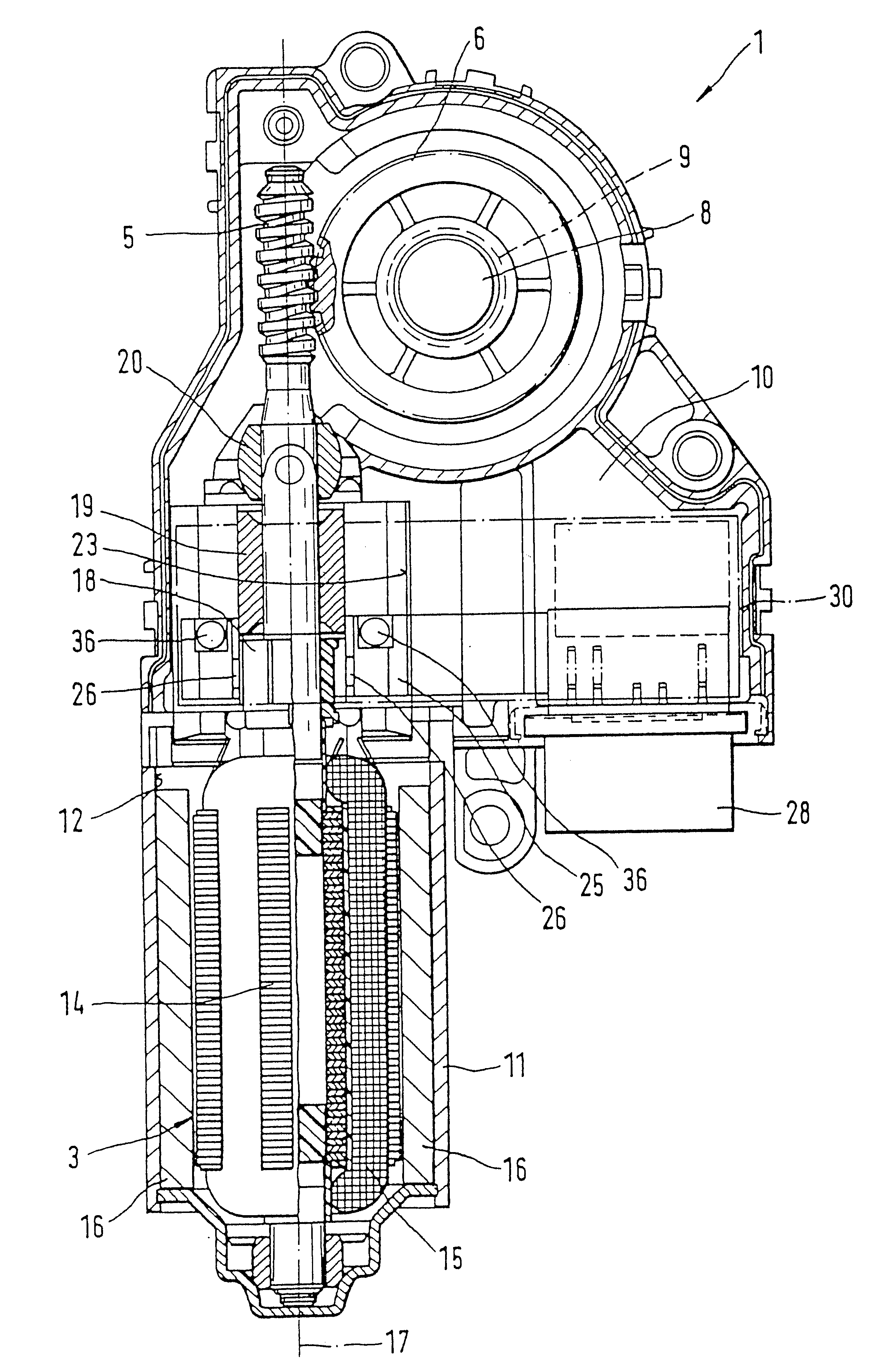
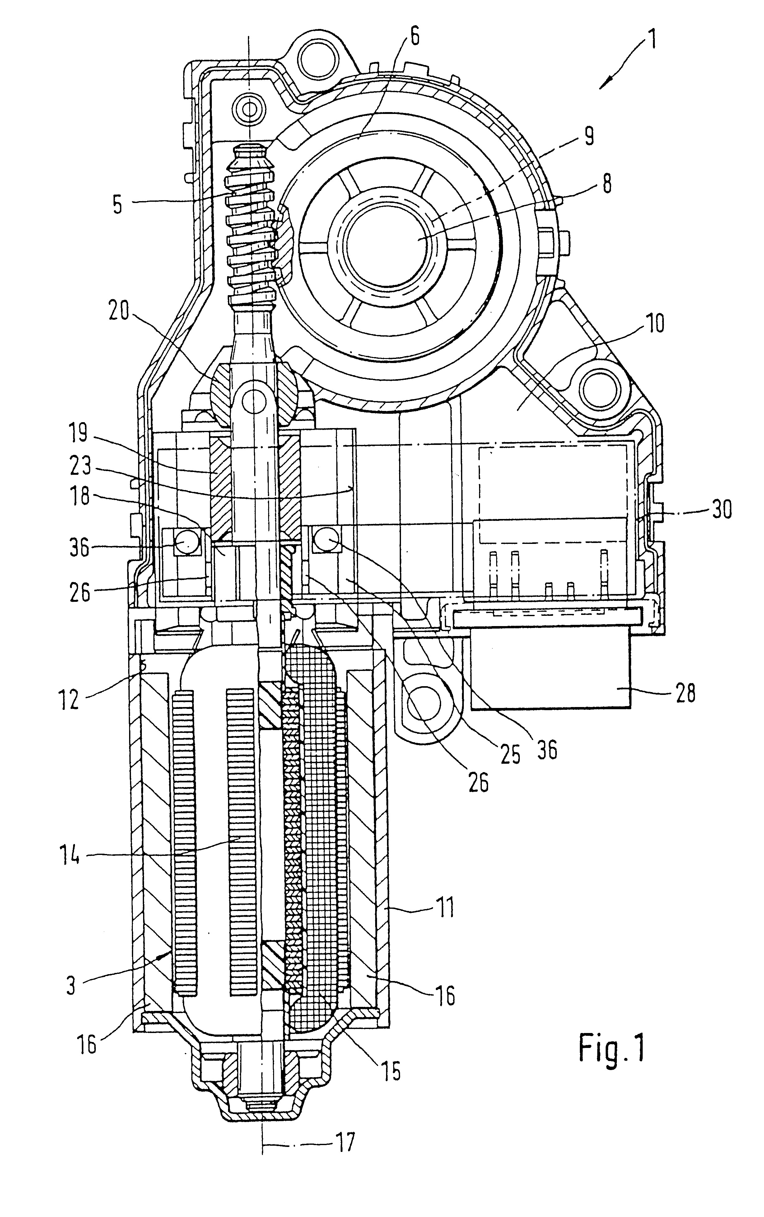
FIG. 1 shows a partially sectional representation of a drive device 1, which is particularly suited for moving a sliding sunroof of a vehicle, in particular a motor vehicle. For this purpose, the drive device 1 has an electric motor 3 with a step-down transmission which is comprised for example of a worm shaft 5 and a worm gear 6 that meshes with the worm shaft 5. The worm gear 6 is connected in a rotationally fixed manner to a drive pinion 9, which is affixed to a shaft 8 and is drawn with dashed lines in FIG. 1, which for its part, by way of a mechanism that is not shown in detail, can open or close a sliding sunroof of the vehicle, also not shown in detail. By way of a decoupling mechanism, which is comprised for example of a driving pin that is not shown in detail and can be correspondingly actuated by a tool, it is possible to interrupt the rotationally fixed connection of the worm gear 6 to the drive pinion 9. The step-down transmission 5, 6 is accommodated in a transmission h...


PUM


Abstract

A brush holder equipped as a component on a printed circuit board and is inserted into a recess provided in a transmission housing of the drive device and thereby can be slid in the radial direction over a commutator of an already completely assembled armature. The drive device according to the invention is provided for moving a sliding sunroof of a vehicle.

Description

PRIOR ARTThe invention is based on a drive device, in particular for moving a sliding sunroof of a vehicle. A drive device has already been disclosed (European Patent Document 0 474 904), which is used to drive a window lifter. The drive device has a base housing, which is injection molded in one piece and is comprised of a transmission housing and an electronics housing. An electric motor which has an armature is affixed to the housing. The armature is accommodated in a cup-shaped pole housing, whose open end face is screw connected to the base housing. The armature also has a commutator which is disposed outside the pole housing in the base housing. An end region of the armature, which region adjoins the commutator, is thereby embodied in the form of a transmission drive shaft for a transmission and in this connection, has the form of a worm shaft, for example. In addition, a printed circuit board is accommodated in the base housing, which has a narrow strut that protrudes lateral...

Claims


Application Information

Patent Timeline
IPC IPC(8): H02K5/14H02K23/66H02K11/02H02K7/116H02K5/22B60J7/057F16H1/16H02K11/026H02K23/00
CPCH02K5/148H02K11/026H02K23/66F16H1/16H02K5/225H02K7/1166H02K2205/06H02K2211/03
Inventor KLAPPENBACH, CHRISTOPHSPINNER, KLAUSHEITZ, ROBERTHILS, ALOISBAEUERLE, CHRISTIANDREIER, FRIEDRICH-WILHELM
Owner ROBERT BOSCH GMBH
Why Eureka
Try Eureka