Method and apparatus for routing low-skew clock networks

a low-skew clock and network technology, applied in the direction of generating/distributing signals, pulse techniques, instruments, etc., can solve the problems of increasing power requirements, reducing wireability, and increasing wire and capacitance,

Inactive Publication Date: 2001-03-20
IBM CORP
View PDF5 Cites 74 Cited by
  • Summary
  • Abstract
  • Description
  • Claims
  • Application Information

AI Technical Summary

Problems solved by technology

Mesh or grid methods are often simple to lay out, but have greater amounts of wire and higher capacitance than is necessary, which increases power requirements and reduces wireability.
This problem is compounded when multiple clock domains are required, which is very common in a large variety of ASICs.
Such wide wires are more susceptible to inductance at high frequency, which limits the latency or performance of the clock distribution network.
Conventional "H" trees are often driven from a localized source, causing noise or power supply dips.
These steps can delay design schedules and limit floor plan changes.
Electromigration problems are also aggravated by localized wiring and sources.
Additionally, spines, or fishbones, have resistance / capacitance (RC) drops across them, which causes undesirable clock skew.
Distributed buffers (with or without balanced routing) suffer from process variations and added latency, increasing skew and decreasing performance.
Further, inductance effects often go unnoticed in narrow single wires because the resistance is much greater than the inductive-reactance term.
If this inductance is not considered, large errors in delays can result.
The difference in latency can result in skew if wide wires are used on some networks and narrow wires are used on other networks.
Wide wires can have additional delay differences if return paths are not modeled correctly.

Method used


Image

  • Method and apparatus for routing low-skew clock networks
  • Method and apparatus for routing low-skew clock networks
  • Method and apparatus for routing low-skew clock networks

Examples


Embodiment Construction

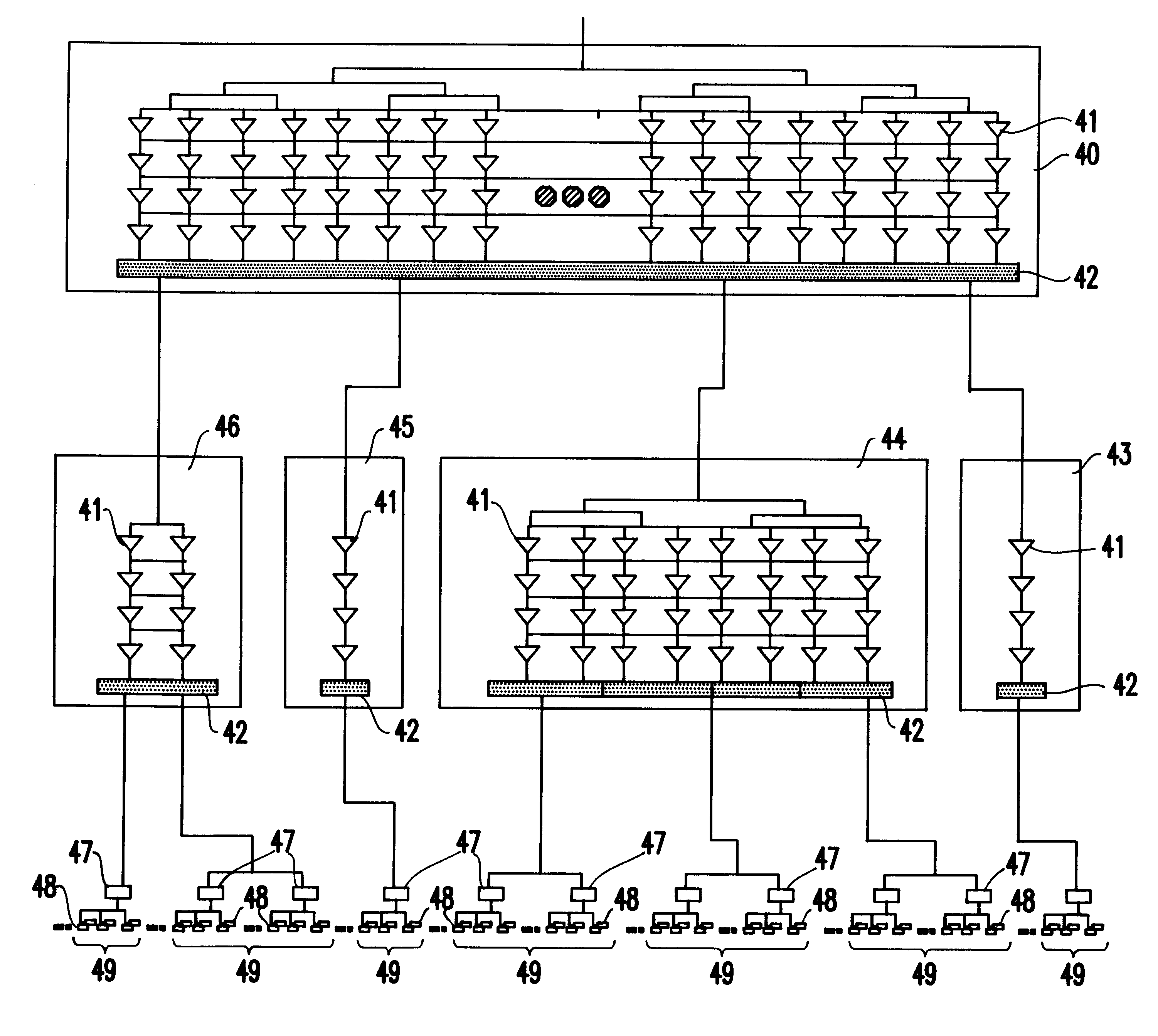
Application specific integrated circuits (ASICs) are generally produced in smaller numbers when compared to standardized integrated circuits because of their application specific nature. Thus, the design cost per unit produced is higher for ASICs than for more standardized integrated circuits.

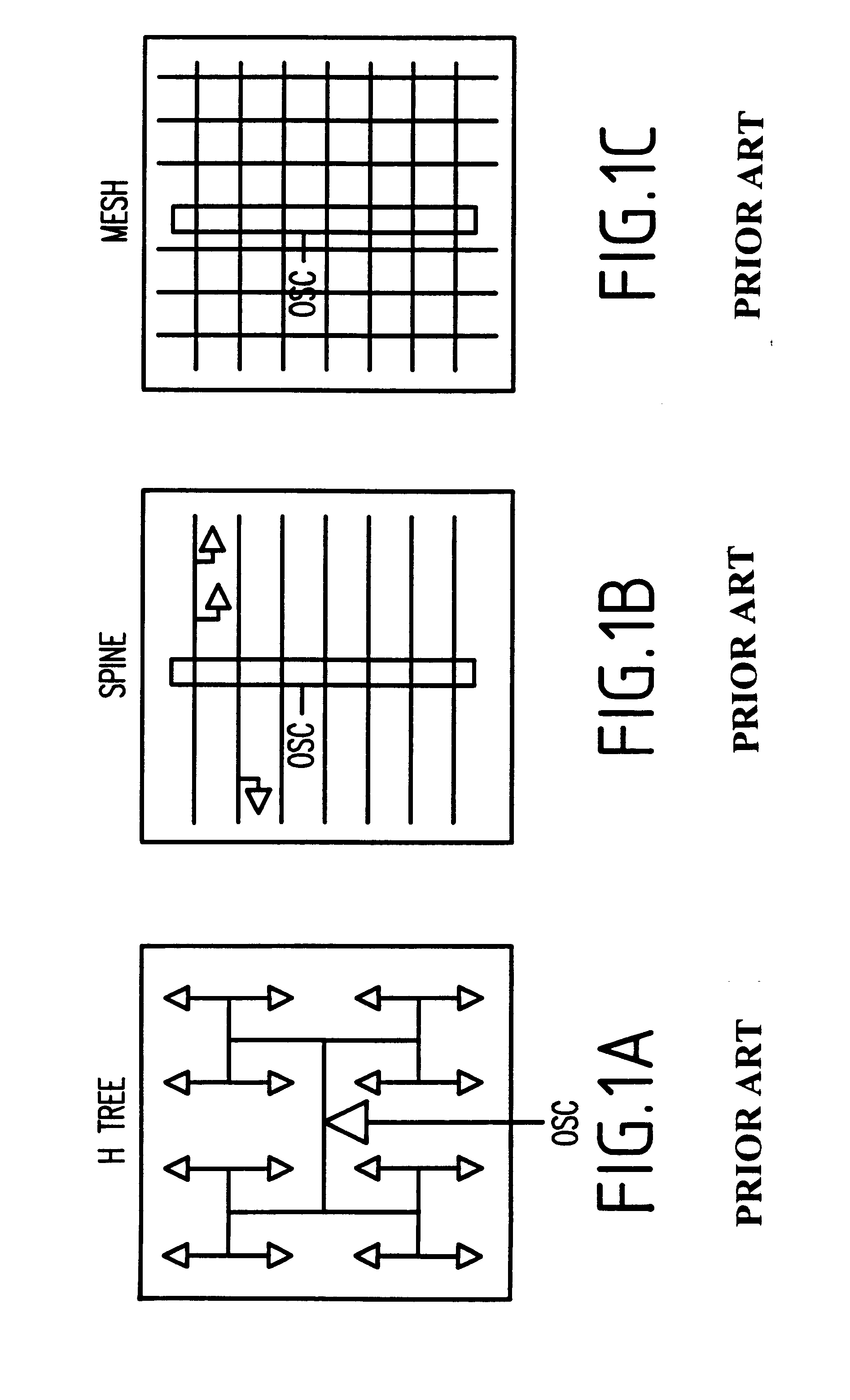
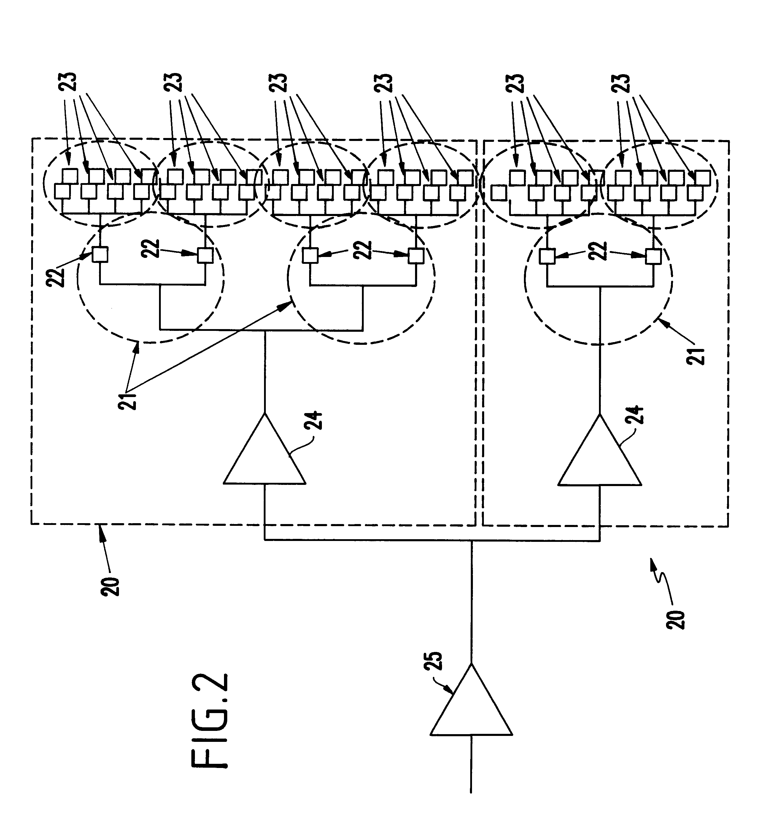
The design of the clock distribution networks for ASICs contributes a large amount to this design cost. Traditionally, designers of ASIC products have preferred distributed clock trees because of their flexibility. More specifically, the flexibility afforded by clock distribution trees reduces the design time and the accompanying design cost of ASICs.

However, as mentioned above, distributed clock trees present the designer with the disadvantages associated with a large number of stages which causes increased clock skew due to process variation and increased latency. Therefore, conventional clock network design presented a tradeoff between design cost and circuit complexity / performance. Often, b...


PUM


Abstract

An integrated circuit chip comprises a plurality of clock distribution sub-networks each including a clock input for receiving a clock signal, each of the clock distribution sub-networks having a capacitance, as seen from the clock input, substantially equivalent to others of the clock distribution sub-networks; and a structured clock buffer having a size based on a load of the clock distribution sub-networks, and providing the clock signal to the clock distribution sub-networks.

Description

1. Field of the InventionThe present invention generally relates to methods and structures for distributing clock signals within a semiconductor processor environment and, more particularly, to a methodology for growing and inserting clock trees on high-performance, low power application specific integrated circuit (ASIC) chips.2. Description of the Related ArtBalanced clock distribution networks have historically fallen into four categories--meshes or grids, "H" or "I" trees, spines, and distributed buffers with or without balanced wiring. For example, FIG. 1(a) illustrates an "H" tree, FIG. 1(b) illustrates a spine structure and FIG. 1(c) illustrates a mesh layout.Mesh or grid methods are often simple to lay out, but have greater amounts of wire and higher capacitance than is necessary, which increases power requirements and reduces wireability. This problem is compounded when multiple clock domains are required, which is very common in a large variety of ASICs.The "H" or "I" tree...

Claims


Application Information

Patent Timeline
Patent Type & Authority Patents(United States)
IPC IPC(8): G06F1/10
CPCG06F1/10G06F17/5077G06F2217/62G06F30/394G06F30/396
Inventor ADAMS, JANICE M.CARRIG, KEITH M.GREGOR, ROGER P.MENARD, DANIEL R.
Owner IBM CORP
Why Eureka
Try Eureka