Method of manufacturing a high heat flux regenerative circuit, in particular for the combustion chamber of a rocket engine

a high heat flux regenerative circuit and combustion chamber technology, which is applied in the direction of rocket engine plants, machines/engines, mechanical apparatus, etc., can solve the problems of long operation time, high cost, and inability to meet the requirements of production, and achieve the effect of optimizing the characteristics of manufactured structures

Inactive Publication Date: 2001-04-03
SN DETUDE & DE CONSTR DE MOTEURS DAVIATION S N E C M A
View PDF8 Cites 21 Cited by
  • Summary
  • Abstract
  • Description
  • Claims
  • Application Information

AI Technical Summary

Benefits of technology

The object of the invention is to remedy the above-specified drawbacks and to enable regenerative circuit structures to be manufactured in a manner that is more convenient than in prior art methods while also making it possible to optimize the characteristics of the manufactured structures, even when the structures are of large dimensions and are subjected to high heat flux densities.
the step of eliminating the soluble inserts from the channels in the body of the structure or from channels formed around the core is performed by circulating a fluid such as hydrochloric acid.
Thus this variant of the first embodiment of the method according to the invention allows to make radial fins of small height which avoid the need of forming on the intermediate layer a thermal barrier by spraying a layer of material, but the fins do not delimit main channels opening out to face the intermediate layer. The main channels are formed by machining in the core from the outside.

Problems solved by technology

Those operations are lengthy and expensive.
Furthermore, each of the welds 110 used for final assembly of the components of the chamber constitutes a potential risk of breakage.
Nevertheless, known methods remain relatively unsatisfactory, in particular because of the slowness of the process whereby the inserts are dissolved and the temporary layers are eliminated, and because of difficulties in making structures that are of large dimensions in satisfactory manner.

Method used


Image

  • Method of manufacturing a high heat flux regenerative circuit, in particular for the combustion chamber of a rocket engine
  • Method of manufacturing a high heat flux regenerative circuit, in particular for the combustion chamber of a rocket engine
  • Method of manufacturing a high heat flux regenerative circuit, in particular for the combustion chamber of a rocket engine

Examples


Embodiment Construction

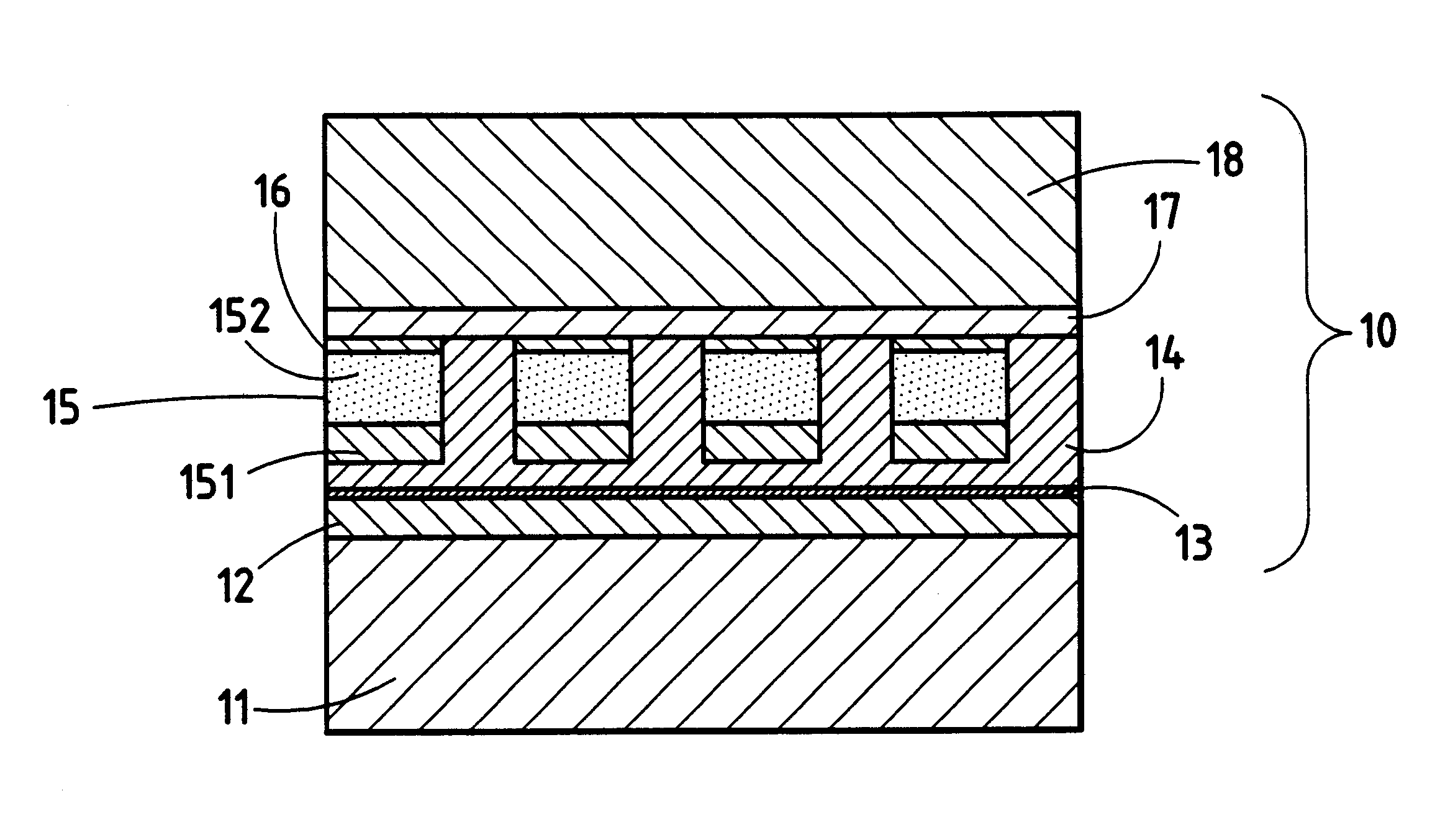
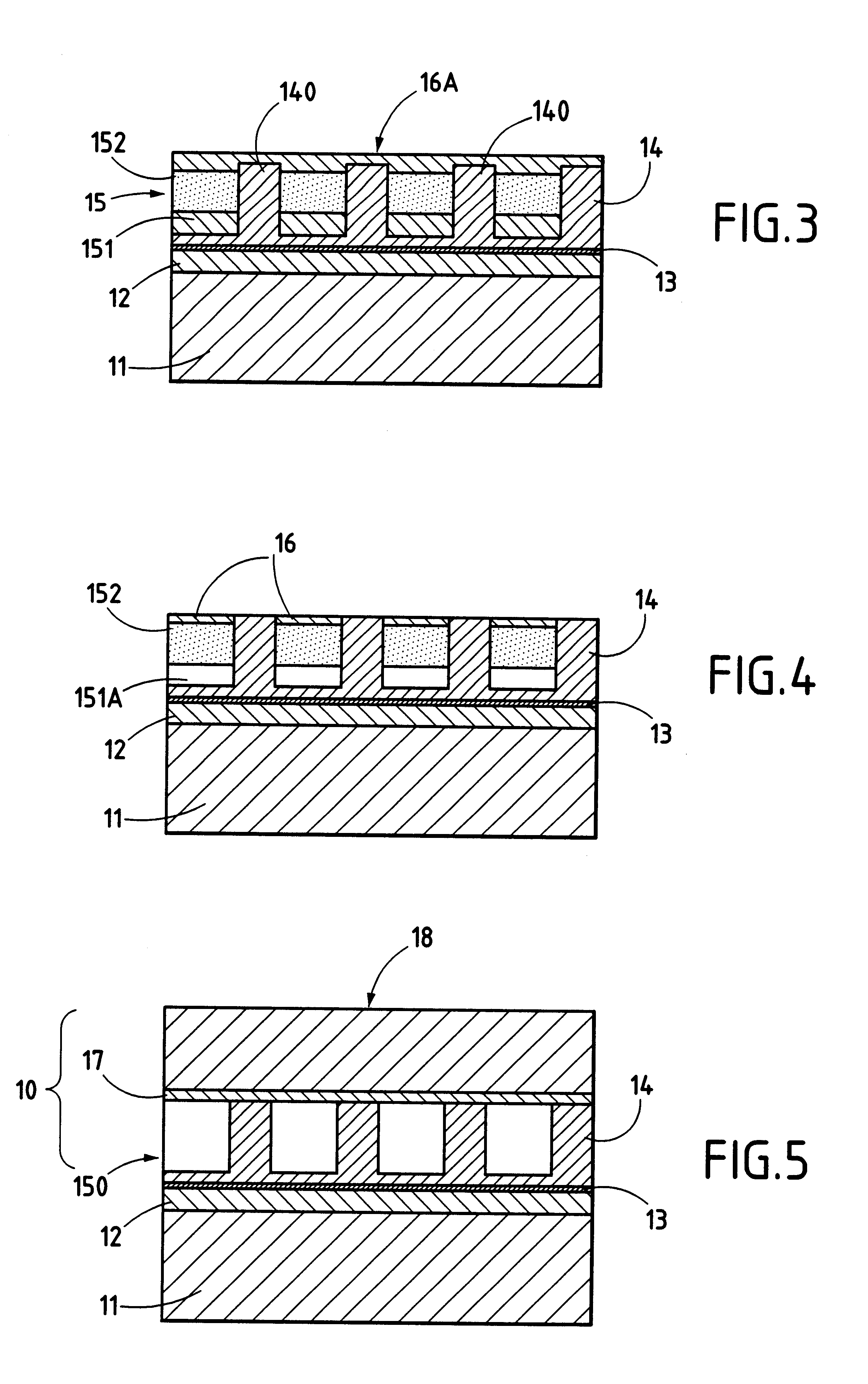
Particular implementations of the method of the invention are described with reference to manufacturing high heat flux regenerative circuits constituted by hollow structures defining rocket engine combustion chambers or nozzles.

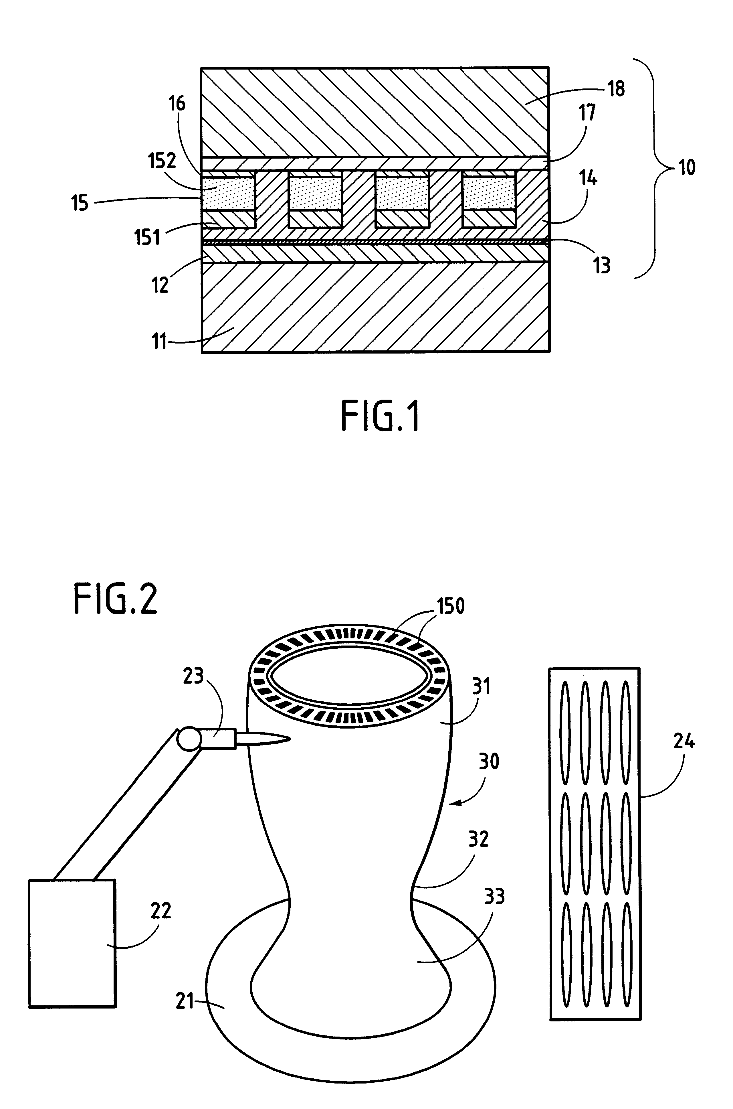
FIG. 2 shows an hourglass-shaped example of such a rocket engine nozzle 30 comprising, in conventional manner, an upstream portion 31 forming a combustion chamber proper which converges towards a throat 32, which is in turn extended by a diverging downstream portion 33. For a rocket engine that uses liquid propellant, the propellant components are injected into the upstream portion 31 that forms the combustion chamber, and the gases that result from the combustion are evacuated via the throat 32 and the diverging portion 33 of the nozzle so as to generate the required thrust force. The wall of the nozzle 30 is provided with channels 150 that extend essential longitudinally and that convey a cooling fluid, which fluid may be one of the propellant components, f...


PUM

PropertyMeasurementUnit
temperatureaaaaaaaaaa
grain sizeaaaaaaaaaa

Abstract

A regenerative circuit structure is built up by implementing the following steps in particular:an intermediate layer is made on a support core representing the inner profile of the structure;a series of channels regularly distributed around the core is made with the channels opening to face the intermediate layer, each of the channels being provided with a soluble insert;the support core is preheated and the body of the structure is made by thermal spraying under a vacuum;channels are machined in the body from the outside, and said channels are filled by means of soluble inserts;a closure layer is formed to close the channels in the body, and an outer envelope is formed by thermal spraying under a vacuum, after preheating; andall of the soluble inserts and the intermediate layer are eliminated.

Description

The present invention relates to a method of manufacturing a high heat flux regenerative circuit comprising a structure having an inner functional surface in contact with a first fluid and a set of channels formed in the body of the structure for conveying a second fluid in heat exchange relationship with the first fluid, the method consisting in using thermal spraying and machining operations around a reusable support core to build up the structure from said inner functional surface.The invention also relates to a high heat flux regenerative circuit obtained by the method, such as the rocket engine combustion chamber.Structures constituting high heat flux regenerative circuits are used in various contexts, for example in heat exchangers, in turbine blades cooled by a circulating liquid, or in the walls of combustion enclosures.Thus, combustion enclosures, such as the combustion chambers and nozzles of rocket engines, in particular engines using liquid propellants, have walls which ...

Claims


Application Information

Patent Timeline
Patent Type & Authority Patents(United States)
IPC IPC(8): B23P15/26B23P15/00C23C4/12F02K9/00F02K9/64
CPCB23P15/008B23P15/26F02K9/64C23C4/128Y10T29/49346Y10T29/49336C23C4/137
Inventor CORNU, DANIELVERDY, CHRISTOPHEDE MONICAULT, JEAN-MICHELCODDET, CHRISTIAN
Owner SN DETUDE & DE CONSTR DE MOTEURS DAVIATION S N E C M A
Why Eureka
Try Eureka