Heat exchanger having several heat exchanging portions

a heat exchanger and heat exchange portion technology, applied in the field of heat exchangers, can solve the problems of reducing the loss of heat in this core portion, the above-described method of setting the fin pitch in the first and second core potions cannot be applied to this type of heat exchanger, and the inability to design each fin pitch independently

Inactive Publication Date: 2001-04-03
DENSO CORP
View PDF6 Cites 40 Cited by
  • Summary
  • Abstract
  • Description
  • Claims
  • Application Information

AI Technical Summary

Problems solved by technology

However, in the heat exchanger in which different core portions are integrated and cooling fins of first core portion and second core portion are integrated with each other, each fin pitch cannot be designed independently respectively.
Therefore, the above-described method of setting the fin pitches in the first and second core potions respectively cannot be applied to this type heat exchanger.
However, the pressure loss in this cor

Method used


Image

  • Heat exchanger having several heat exchanging portions
  • Heat exchanger having several heat exchanging portions
  • Heat exchanger having several heat exchanging portions

Examples


first embodiment

(First Embodiment)

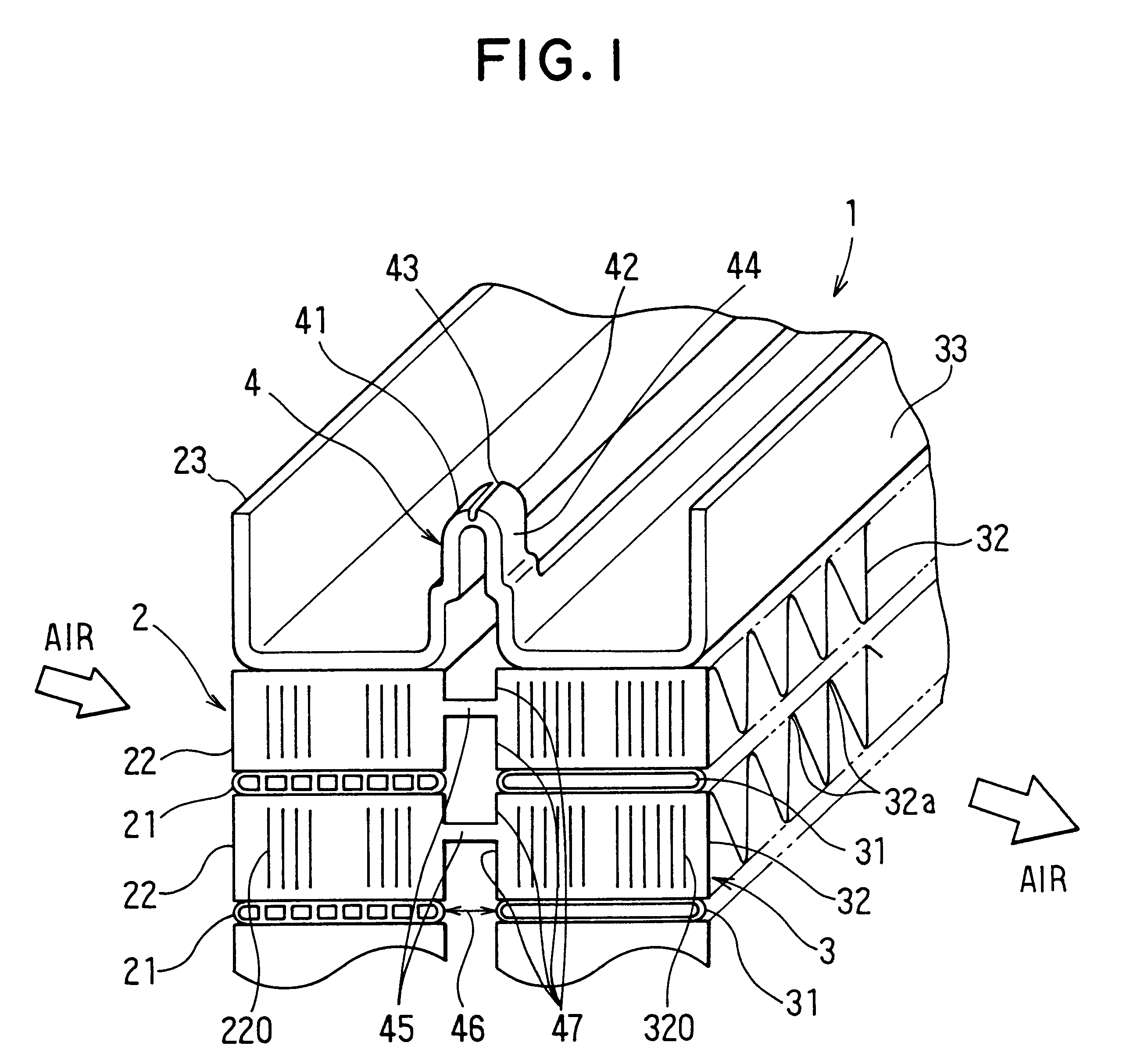
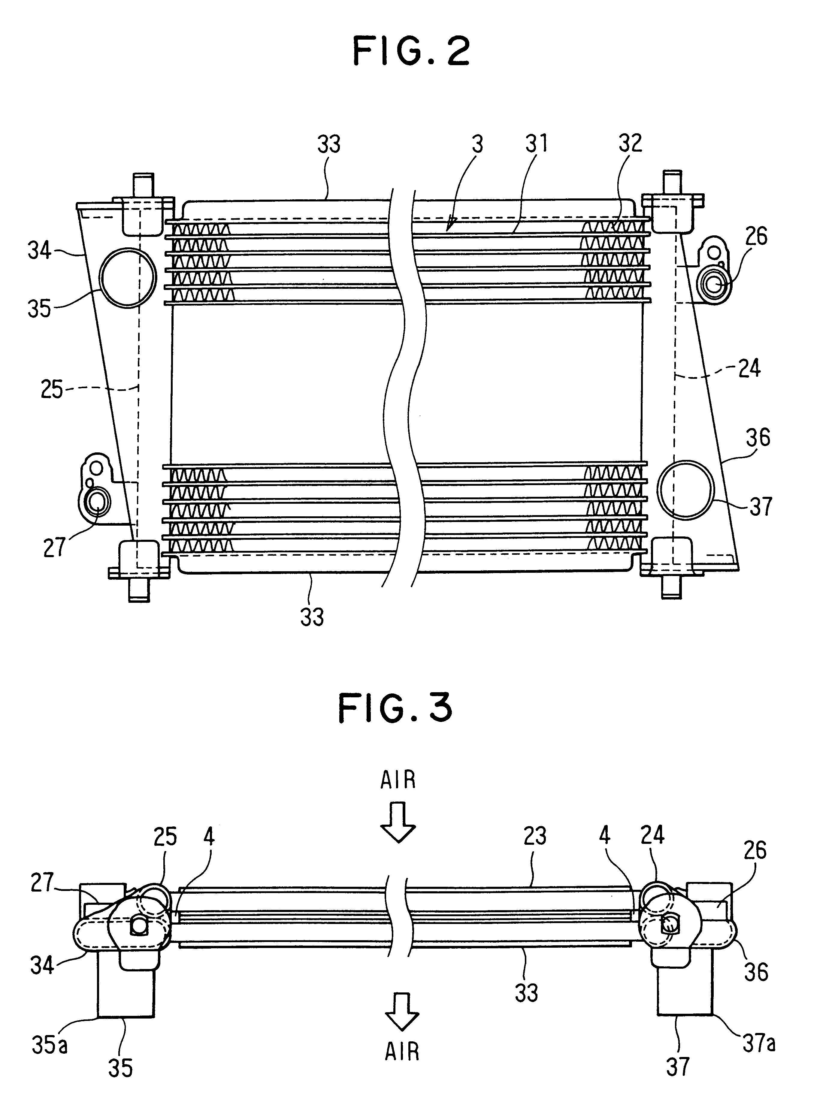
In an automotive heat exchanger 1 shown in FIGS. 1,2, a condenser core portion 2 of an automotive air conditioning apparatus is used as a first core portion, and a radiator core portion 3 for cooling an engine is used as a second core portion. Generally, because the temperature of refrigerant flowing through the condenser core portion 2 is lower than that of engine cooling water flowing through the radiator core portion 3, the condenser core portion 2 is disposed at the upstream air side of the radiator core portion 3 in air flow direction and the two core portions 2, 3 are disposed in series in the air flow direction at the front-most portion of an engine compartment. The structure of the heat exchanger of the first embodiment is hereinafter described with reference to FIGS. 1 through 5.

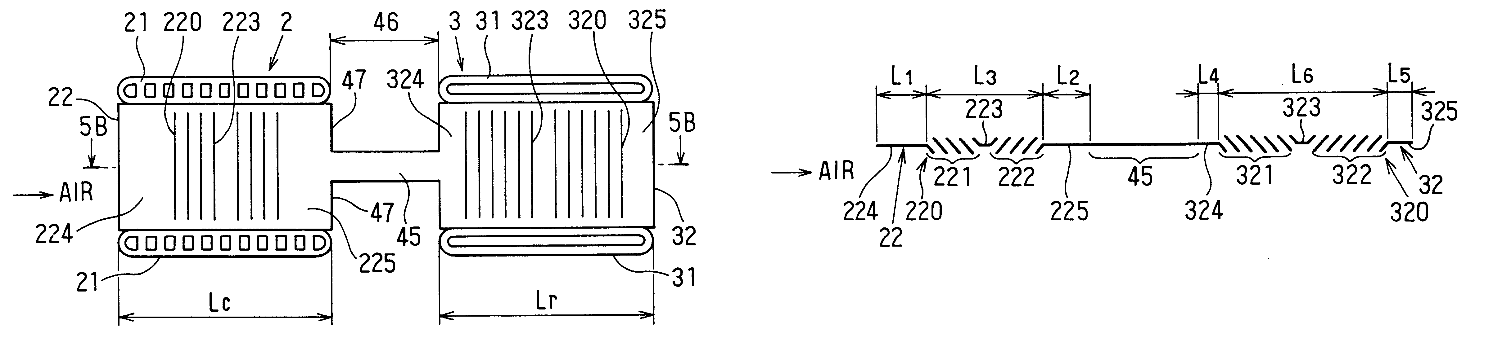
FIG. 1 is a partial enlarged cross-sectional view of a heat exchanger 1 of the present invention. As shown in FIG. 1, a condenser core portion 2 and a radiator core portion 3 are d...

second embodiment

(Second Embodiment)

According to the second embodiment, as shown in FIGS. 6A, 6B, in the condenser cooling fin 22, ten louvers 220 are provided by making the most of the space thereof. While, in the radiator cooling fin 32, six louvers 320 are provided although ten louvers can be provided thereon if desired. That is, the relation: (Nc / Lc)>(Nr / Lr) is satisfied. Thereby, the radiation amount in the radiator core portion 3 decreases, while the radiation amount in the condenser core portion 2 increases with the air flow amount increasing.

FIG. 7 shows the relations between the number of louvers decreasing ratio and the performance ratios of the core portions 2, 3 under the condition that air flow speed of the cooling air is constant. Here, the number of louvers decreasing ratio is defined as a ratio of the number of louvers decreased relative to the number of louvers which can be provided within the predetermined fin width Lc, Lr. For example, in the condenser cooling fin 22 shown in FIG....

third embodiment

(Third Embodiment)

According to the third embodiment, as shown in FIGS. 8A, 8B, a projection portion 326 is formed at the air upstream side end (the end facing the condenser core portion 2) of the radiator cooling fin 32. This projection portion 326 protrudes from the end of the radiator tube 31 toward the air upstream side. Thereby, the number of louvers Nr in the radiator cooling fin 32 is increased more than that in the first embodiment.

For example, as shown in FIGS. 8A, 8B, the radiator cooling fin 32 has twelve louvers 320. Thus, a radiation amount difference between in the condenser core portion 2 and in the radiator core portion 3 is expanded more than in the first embodiment.


PUM


Abstract

A ratio (Nc/Lc), in a condenser core portion, of the number of louvers to a width of a condenser cooling fin, and a ratio (Nr/Lr), in a radiator core portion, of the number of louvers to a width of a radiator cooling fin satisfy that the ratio in one core portion, out of the condenser and the radiator core portions, a required radiation amount of which is larger than that of the other core portion is larger than the ratio in the other core portion. Thus, in the core portion having a small required radiation amount, the number of louvers relative to the width of the cooling fin is small thereby decreasing the heat transfer ratio. However, by this, the air flow resistance in this core portion decreases thereby increasing an air flow amount. Thus, the radiation amount of the core portion of which required radiation amount is large increases.

Description

1. Field of the InventionThe present invention relates to a heat exchanger in which different core portions are integrated with each other, and more particularly the present invention relates to a heat exchanger which can be effectively applied to a radiator of an automotive engine and a condenser of an automotive air conditioning apparatus.2. Description of Related ArtConventionally, an automotive air conditioning apparatus is assembled into a vehicle at a car dealer or the like after the vehicle has been completed. Recently, however, the automotive air conditioning apparatus is generally installed in the vehicle during vehicle assembling process. Therefore the automotive air conditioning apparatus is assembled with automotive parts in the assembling process of the vehicle at the manufacturing plant.A heat exchanger in which different core portions such as a radiator and a condenser are integrated is disclosed in Japanese Patent Publication No. 3-177795. In this heat exchanger, coo...

Claims


Application Information

Patent Timeline
IPC IPC(8): F28F1/12F28D1/04
CPCF28D1/0435F28F1/128F28D2021/0084F28D2021/0094F28F2215/02F28F2215/04
Inventor SUGIMOTO, TATSUOSUZUKI, SHINOBUSAKANE, TAKAAKIYAMANAKA, YASUTOSHI
Owner DENSO CORP
Why Eureka
Try Eureka