Apparatus for use in magnetic-field detection and generation devices

a technology of magnetic field detection and generation device, applied in the direction of magnetic field measurement using superconductive devices, magnetic field measurement using permanent magnets, instruments, etc., can solve the problem of limited resolution of read/write heads of magnetic storage devices

Inactive Publication Date: 2001-04-03
IBM CORP
View PDF5 Cites 39 Cited by
  • Summary
  • Abstract
  • Description
  • Claims
  • Application Information

AI Technical Summary

Problems solved by technology

In a similar way, the resolution of read/write heads for magnetic

Method used


Image

  • Apparatus for use in magnetic-field detection and generation devices
  • Apparatus for use in magnetic-field detection and generation devices

Examples


Embodiment Construction

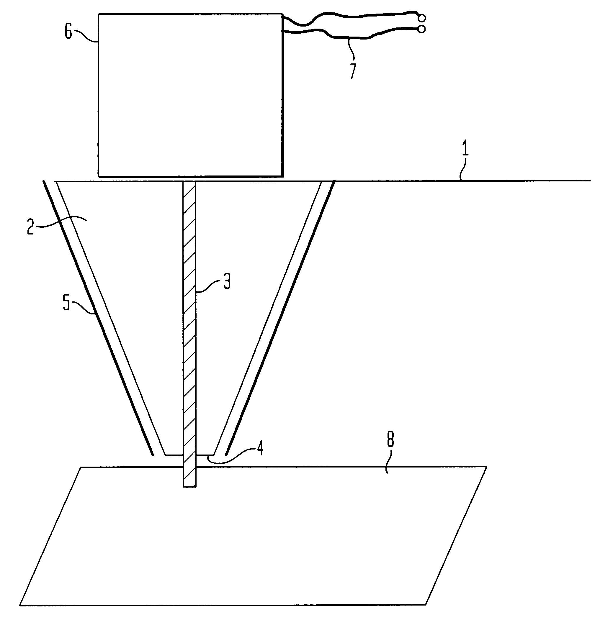
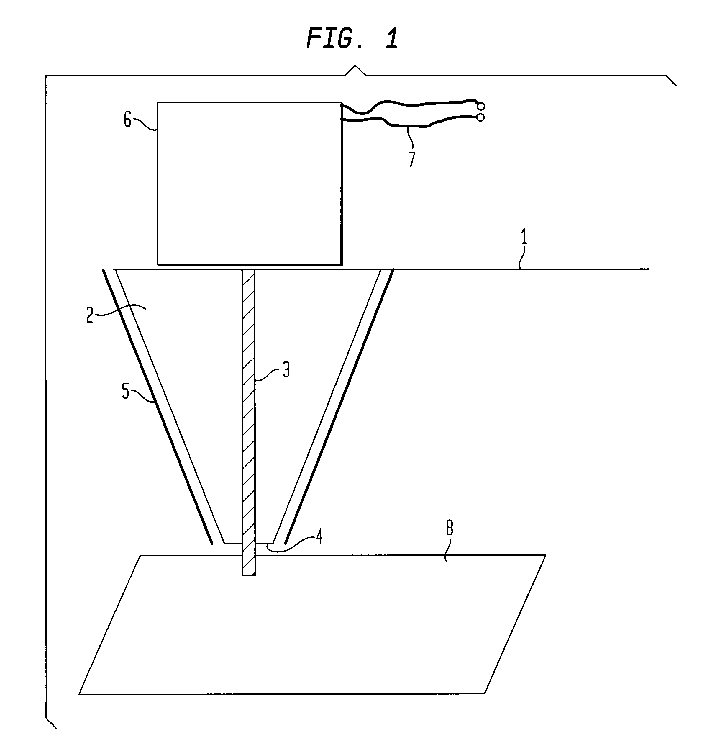
The FIGURE schematically shows the free end of a cantilever 1 of an AFM with a conical tip 2 at this free end. The tip 2 is made of a semiconductive material with a conventional silicon-manufacturing technique. Any other non-ferromagnetic material can also be used, f.i. SiN. Along the axis of the semiconductive tip 2, a longitudinal member in form of a narrow filament 3 made of a softferromagnetic material with a high permeability is embedded. The filament material is a Ni-Fe alloy with a typical (bulk) permeability value above 10.sup.4. Preferred suitable materials are materials known under the name Permalloy (19% Fe, 78% Ni, 3% Mn) or Mumetal (18% Fe, 75% Ni, 5% Cu, 2% Cr). The use of a Permalloy filament 3 inside the tip 2 has various advantages. This way, the width of the filament 3 can be kept very narrow which leads to a high lateral resolution of the apparatus. Further, this design maintains sufficient mechanical strength in order to perform atomic-force microscopy in combina...


PUM


Abstract

A magnetic-field-detecting and/or generating apparatus comprises a non-ferromagnetic tip with a longitudinal member of ferromagnetic material embedded in the tip. Further, magnetic-shield means is arranged around the tip. At the end of the longitudinal member a magnetic-field device is arranged. The same principle can be applied to read/write heads for use in magnetic-storage devices.

Description

TECHNICAL FIELDThis invention refers to a magnetic-field-detecting and / or generating apparatus. More particularly, the invention relates to a scanning superconducting quantum interference device (SQUID) microscope (SSM) and a read / write head for use in magnetic storage devices.PRIOR ARTAn AFM is a device which uses a tip with a very sharp apex and low-range atomic forces to investigate the surface of a sample down to atomic dimensions. Such a device is described in U.S. Pat. No. 4,724,318 by Binnig et al. and in various other patent publications. Basically, this device has the tip mounted at a flexible cantilever which is attached to a probe holder and the vertical deflection of the tip is sensed by a detector. A commonly used operation mode of this microscope is to scan the tip over the sample while keeping the force between the tip and the surface constant by moving either the sample or the tip up and down, such that the deflection of the cantilever remains constant. In this way, ...

Claims


Application Information

Patent Timeline
IPC IPC(8): G01R33/035G01R33/038G11B5/00G11B5/127G11B9/00
CPCG01Q60/56G01R33/0358G01R33/0385G11B5/00G11B5/127B82Y35/00B82Y10/00B82Y25/00G01Q80/00G11B9/14G11B9/1409G11B2005/0002Y10S977/948Y10S977/86Y10S977/849Y10S977/863Y10S977/861Y10S977/865Y10S977/96
Inventor GERBER, CHRISTOPHHILGENKAMP, JOHANNES W.MANNHART, JOCHEN
Owner IBM CORP
Why Eureka
Try Eureka