Method for linear friction welding and product made by such method

a friction welding and linear technology, applied in the field of friction welding, can solve the problems of significant concern over the strength of the stub, the relatively heavy assembly, and the difficulty and cost of stub fabrication

Inactive Publication Date: 2001-04-24
UNITED TECH CORP
View PDF14 Cites 76 Cited by
  • Summary
  • Abstract
  • Description
  • Claims
  • Application Information

AI Technical Summary

Benefits of technology

Another object of the present invention is to provide an improved process for joining a base for an airfoil to a disk for an integrally bladed rotor assembly in a gas turbine engine.
According to the present invention, a process for joining a base for an airfoil to a disk for an integrally bladed rotor stage in a gas turbine engine includes providing a disk having a radially outer rim with a radially outer surface. The radially outer rim has a slot defined therein by a recessed surface. The process further includes providing a base having a longitudinally extending root portion facing opposite a longitudinally extending support portion for supporting the airfoil. The root portion has a root surface and the support portion has an outer surface. The process further includes bringing the root surface of the root portion into contact with the recessed surface bounding the slot, applying pressure and relative movement between the base and the rim to achieve during welding, substantial contiguity between the root surface and the recessed surface over the area of the recessed surface, resulting in a substantially continuous linear friction weld between the base and the rim.
The present invention provides an improved method for use in fabricating and repairing an integrally bladed rotor stage. Unlike the prior art stub process, the process of the present invention can be used for repair as well as for original equipment manufacture. Further, since the linear friction weld is located in the rim rather than the airfoil, the weld experiences much less stress, e.g., 50% less in the best mode embodiment, during engine operation than the weld of the prior art stub process. Furthermore, because the present invention achieves, during the linear friction welding process, substantial contiguity between the root surface and the recessed surface over the area of the recessed surface, the present invention prevents flash from collecting at the base of the slot. Thus, the resulting weld between the base and the disk is substantially continuous and has less impurities, i.e., higher quality and fewer defects, than the prior art method that uses a root of generally wedge-like form with opposed converging surfaces and an axial slot having opposed diverging surfaces. Furthermore, in an embodiment of the present invention having a slot with a profile of at least substantially piecewise smooth shape and / or a recessed surface with an angle of inclination no greater than about 45 degrees, a bond of even higher quality will result. Substantially piecewise smooth shape is defined herein as a substantially curvilinear or substantially piecewise linear profile that may have corners with angles, although the fewer and the less pronounced any corners the better. Moreover, in the best mode embodiment, the outer surface of the support portion ends up substantially flush with the radially outer surface of the disk, thereby making possible an integrally bladed rotor that weighs significantly less than previous integrally bladed rotor assemblies that use conventional blades having extended roots and platforms. Further, sealing between adjacent blades is generally not required and the edge of the linear friction weld is generally in the flow path.

Problems solved by technology

This type of rotor assembly is relatively heavy, thereby necessitating that the rotor disk be sufficiently sturdy, and thus heavy, in order to accommodate the stresses resulting from the heavy blade.
Fabrication of a disk with stubs is difficult and costly because it requires complex machining, e.g., 5 axis milling.
Furthermore, there is significant concern over the strength of the stub, i.e., its ability to withstand the linear friction welding process.
Complex (and thus somewhat costly) machining is then used to remove the excess material and thereby obtain a final shape.
In a repair situation, however, the damaged portion is removed, leaving the stub, but the stub is already at its final shape.
Without added measures the final shape stub may not have enough rigidity to withstand the forces needed for linear friction welding.
It may be more costly and difficult to use because it requires four interface surfaces, two on the blade and two on the disk, rather than just two interface surfaces.
Moreover, with this method, flash material, which can contain impurities that cause weld defects, will collect in the bottom of the slot.
Although this flash could be removed, such an operation is expensive and it leaves a hole in the base of the slot.
Further, the use of axial slots may prevent the use of this method for some compressor rotors, because the chord of the airfoils would interfere with linear oscillation of the blade relative to the disc.
However, Petrie et al. do not mention linear friction welding.
Moreover, the integrally bladed disks disclosed by Petrie et al. employ conventional blades having roots, platforms, and airfoils, and thus they do not offer the major advantage sought from an integrally bladed rotor assembly, low weight.

Method used


Image

  • Method for linear friction welding and product made by such method
  • Method for linear friction welding and product made by such method
  • Method for linear friction welding and product made by such method

Examples


Embodiment Construction

.

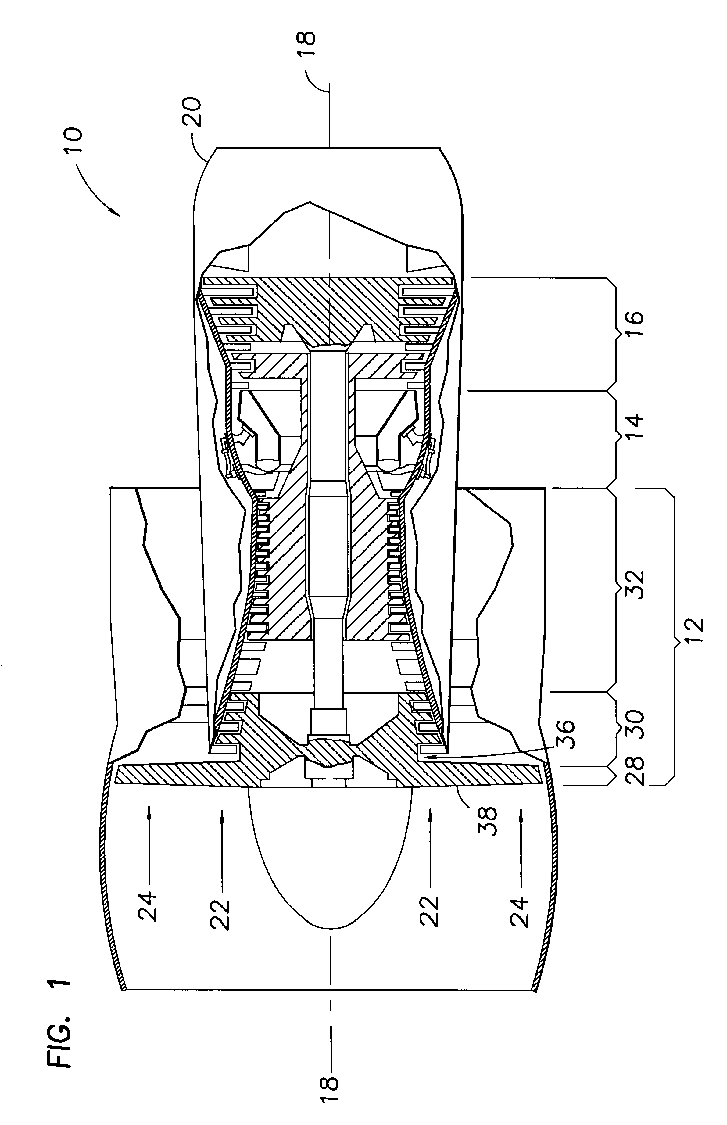
The present invention is disclosed with respect to a best mode embodiment for use in a gas turbine engine of the type illustrated in FIG. 1. Referring now to FIG. 1, a conventional gas turbine engine 10 includes compressor 12, combustor 14, and turbine 16 sections disposed along a longitudinal axis 18 and enclosed in an engine case 20. A primary flow path 22 for working fluid, e.g., air, extends longitudinally along the axis 18. A secondary flow path 24 for working fluid extends parallel to and radially outward of the primary flow path 22.

The compressor 12 may include a fan 28, a low pressure compressor 30, and a high pressure compressor 32. The fan 28 includes a rotor assembly 36 having one or more integrally bladed rotor stages 38.

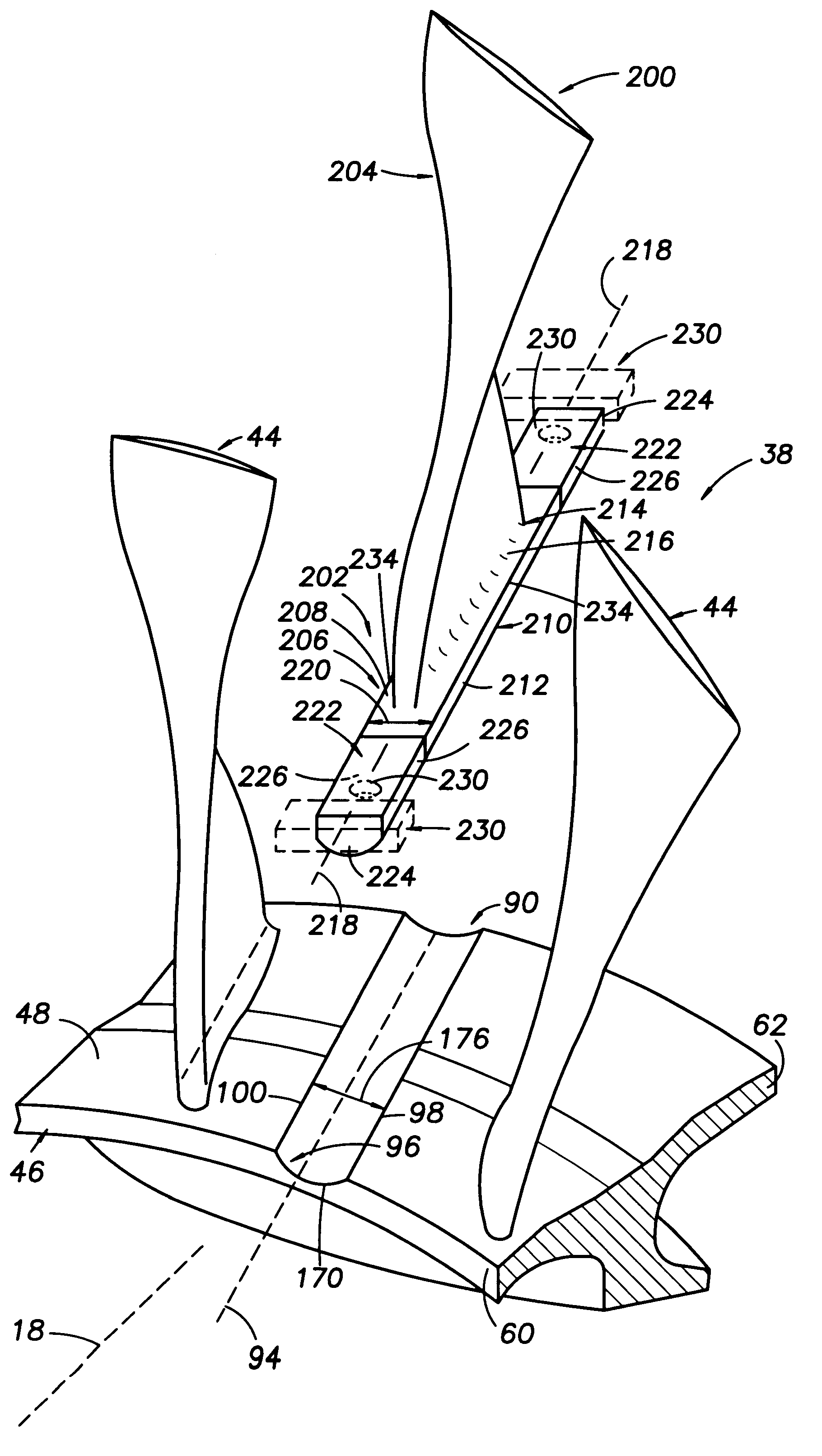
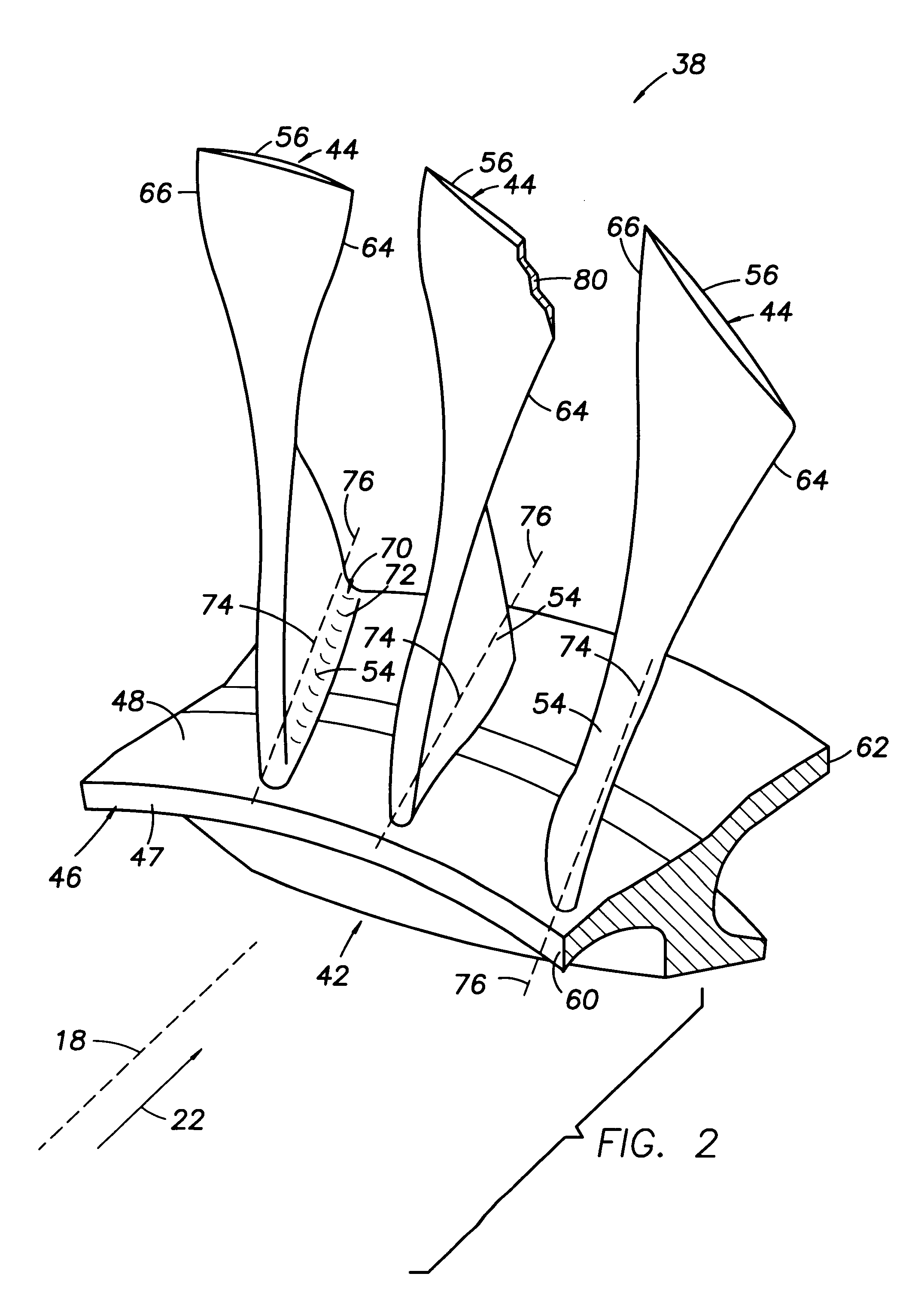
Referring now to FIG. 2, an integrally bladed fan rotor stage 38 comprises a disk 42 and blades 44. The disk 42 has an outer rim 46 having a radially inner surface 47, and a radially outer surface 48. Each of the blades 44 includes an airfoil having a b...


PUM

PropertyMeasurementUnit
anglesaaaaaaaaaa
angleaaaaaaaaaa
angleaaaaaaaaaa

Abstract

A process for joining a base for an airfoil to a disk for an integrally bladed rotor stage in a gas turbine engine includes providing a disk having a radially outer rim with a slot defined therein by a recessed surface, and further includes providing a base having a longitudinally extending root portion facing opposite a longitudinally extending support portion for supporting the airfoil. The root portion has a root surface and the support portion has an outer surface. The process further includes bringing the root surface of the root portion into contact with the recessed surface bounding the slot, applying pressure and relative movement between the base and the rim to achieve during welding, substantial contiguity between the root surface and the recessed surface over the area of the recessed surface, resulting in a substantially continuous linear friction weld between the base and the rim.

Description

DESCRIPTION1. Technical FieldThis invention relates to friction welding.2. Background ArtA typical gas turbine engine has an annular axially extending flow path for conducting working fluid through a compressor section, a combustion section, and a turbine section. The compressor and turbine sections each have a number of bladed rotor assemblies each including a plurality of blades circumferentially spaced about and secured to the radially outer periphery of a rotor disk.In a conventional bladed rotor assembly, the rotor disk has a plurality of axial slots around its radially outer periphery. The blades comprise a root, a platform, and an airfoil. The platform has opposite facing surfaces. The root attaches to one of the surfaces, the airfoil attaches to the other. The slots and the roots have complementary shapes, typically either a dove tail or a fir tree. The root mates with the slot and the blade extends radially outward therefrom. This type of rotor assembly is relatively heavy,...

Claims


Application Information

Patent Timeline
Patent Type & Authority Patents(United States)
IPC IPC(8): B23K20/12F01D5/30
CPCB23K20/1205B23K20/129Y10T29/49339Y10T29/49323Y10T29/49321B23K2201/001B23K2101/001
Inventor WALKER, HERBERT L.HILTON, STEPHEN A.BARBIERI, JOANNFOURNIER, JOHN P.TRASK, RICHARD D.
Owner UNITED TECH CORP
Why Eureka
Try Eureka