Method and apparatus for encoding/decoding n-bit data into 2n-bit codewords

a technology of n-bit data and codewords, applied in the direction of code conversion, dc level restoring means or bias distortion correction, baseband system details, etc., can solve the problems of difficult to implement block coding at high transmission speeds and difficult to implement a simple encoding logic operation

Inactive Publication Date: 2001-05-15
TELEFON AB LM ERICSSON (PUBL)
View PDF11 Cites 35 Cited by
  • Summary
  • Abstract
  • Description
  • Claims
  • Application Information

AI Technical Summary

Problems solved by technology

However, it is difficult to implement block coding at high transmission speeds, for instance in optical high speed systems in the Gbit / s range.
It is particularly difficult to implement a simple encoding logic operation and synchronising logic operation which will allow high speeds.

Method used


Image

  • Method and apparatus for encoding/decoding n-bit data into 2n-bit codewords
  • Method and apparatus for encoding/decoding n-bit data into 2n-bit codewords
  • Method and apparatus for encoding/decoding n-bit data into 2n-bit codewords

Examples


Embodiment Construction

Encoder

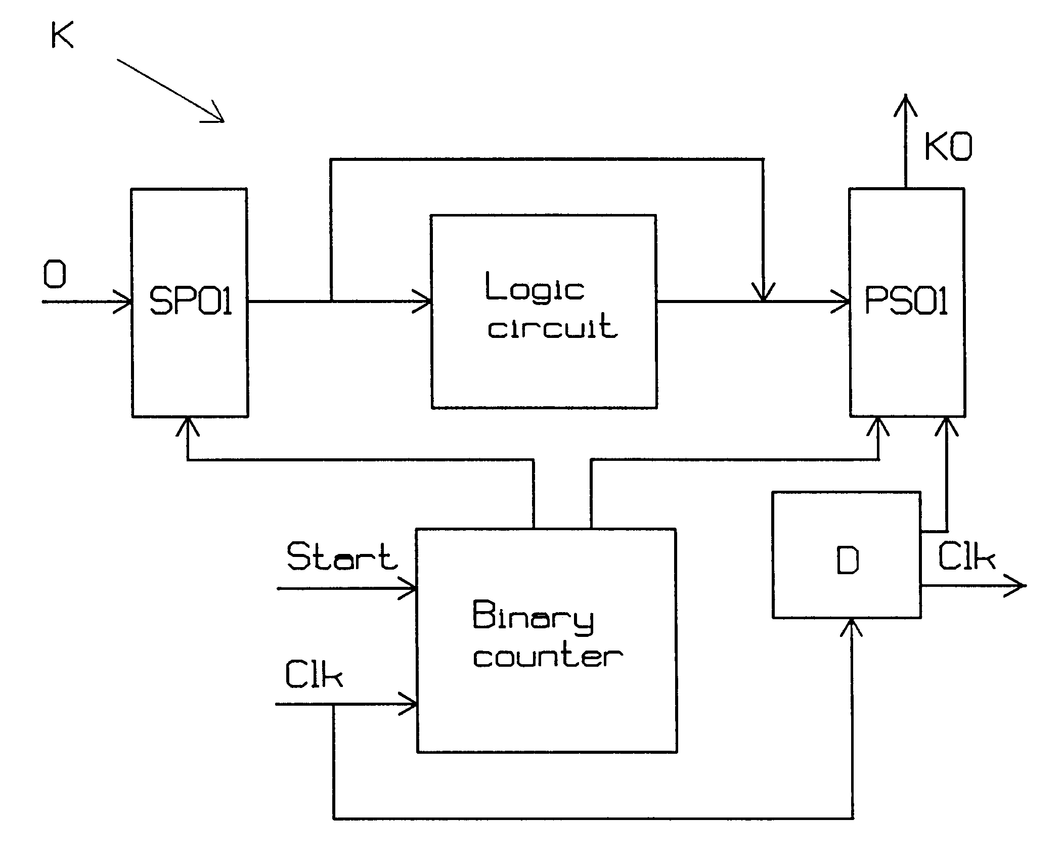
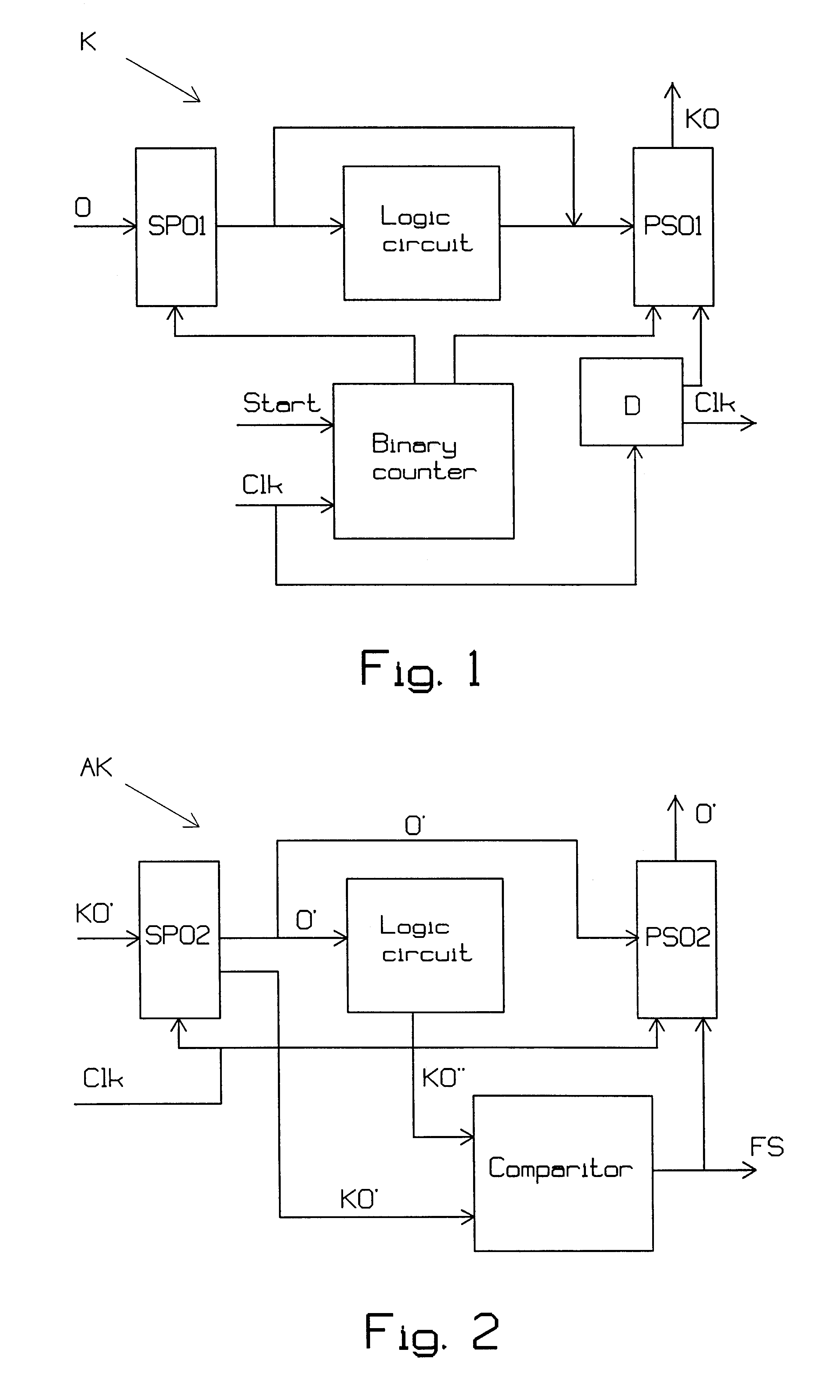
FIG. 1 illustrates an inventive encoder K. The encoder includes a serial-parallel converter SP01, a logic circuit and a parallel-serial converter PS01. Clock signals from a clock Clk are required for synchronizing purposes.

The serial-parallel converter SP01 can be based on a shift register which reads incoming data in groups of N bits, so-called words O, for instance at each positive or negative edge of a clock signal arriving from the clock Clk, wherewith serial-parallel conversion is carried out. The clock signal may have the form of a square wave or a sine wave. Each word O to be encoded is then moved to a second stage in the shift register each Nth period of the clock signal. This sampling signal is generated each Nth period by a binary counter of the frequency divider kind, for instance. The inverted values may also be available on the output of the serial-parallel converter SP01.

The logic circuit reads the N bits of sampled data in the word and generates a complementary...


PUM


Abstract

The present invention relates to the encoding and decoding respectively of serial data, using block codes. Encoding of a serial bit stream of input data in groups of N bits, so-called words (O), to serial output data in groups of 2N bits, so-called code words (KO), is preferably carried out by a logic circuit in a manner such that N of the 2N bits in the code words (KO) are comprised of the N bits input data, unchanged or inverted, and remaining bits in the code words (KO) are determined so that, seen statistically, the code words (KO) will include approximately as many zeros as ones, such that each code word (KO) will be unique for each word (O), and such that at least one of the code words (KO) will remain unique even in bit stream shifting processes. Decoding includes further encoding in a similar logic circuit and comparison of the incoming code words with the code words encoded in the logic circuit, in a predetermined manner.

Description

The present invention relates to an arrangement and to a method for encoding serial data using block code, to an arrangement and method for serial-parallel conversion and decoding of encoded data respectively, and to a transmission system, particularly a multi-channel fibre-optics system, utilizing said encoding facility on at least one transmitter side and said decoding facility on at least one receiver side.DESCRIPTION OF THE BACKGROUND ARTEncoding of a serial data bit stream using block codes, particularly channel encoding, can be effected by dividing the data bit stream into words or blocks, wherein there is added to each block a number of check bits which are solely dependent on the data bits within the block.Encoding is often effected by serial-parallel conversion at the input of an encoder, followed by the performance of logic operations, i.e. the actual encoding process in which the check bits are added. Finally, parallel-serial conversion is effected at the encoder output. ...

Claims


Application Information

Patent Timeline
Patent Type & Authority Patents(United States)
IPC IPC(8): H04L25/49H03M7/14H04L1/00
CPCH04L25/4904H04L25/4908H04L25/06
Inventor DJUPSJOBACKA, ANDERSELLERVEE, PEETERMOKHTARI, MEHRAN
Owner TELEFON AB LM ERICSSON (PUBL)
Why Eureka
Try Eureka