Optical fiber amplifier and optical amplification method

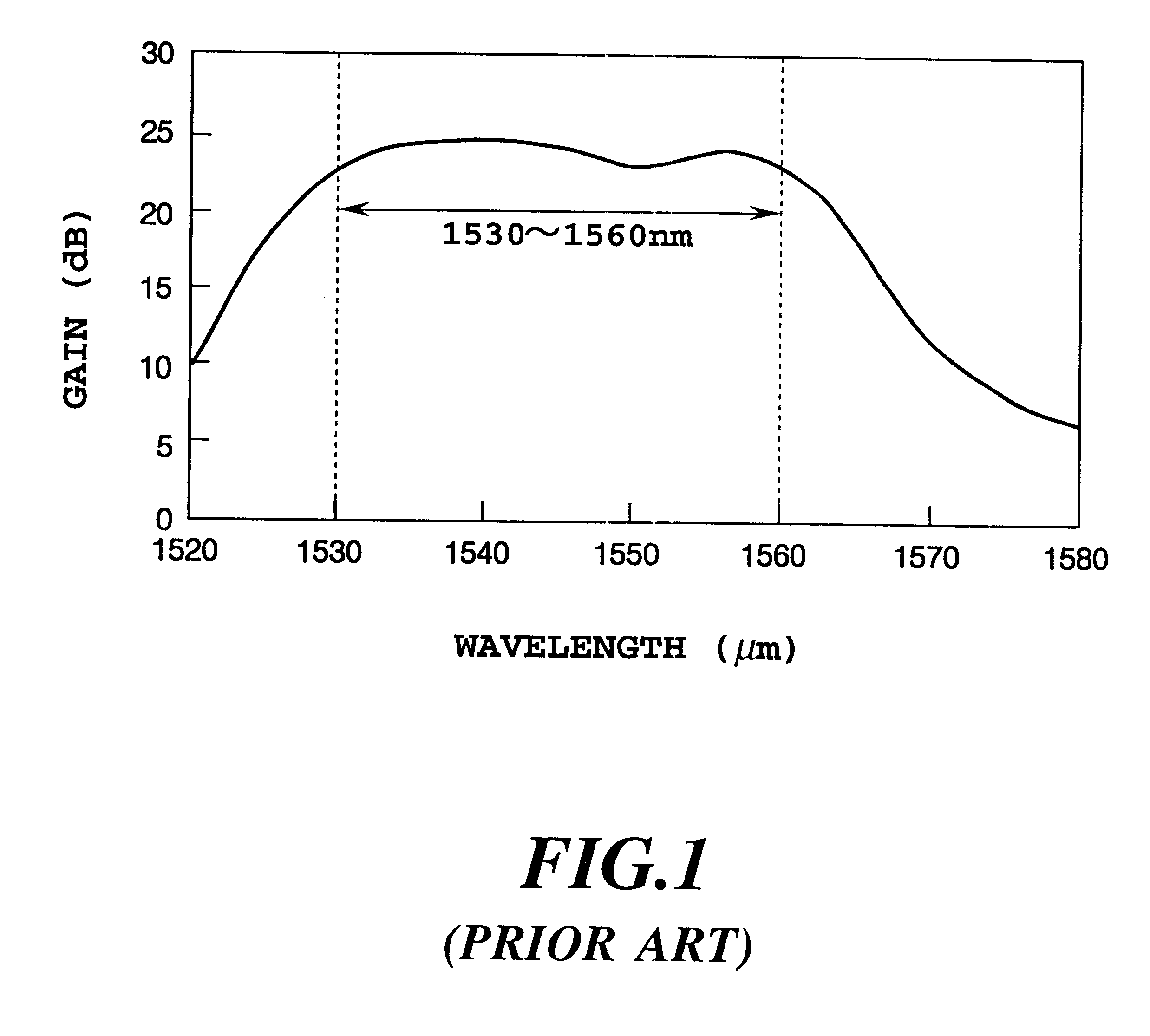
a technology of optical amplifier and optical amplifier, applied in the direction of optical transmission, electromagnetic transmission, active medium material, etc., can solve the problems of source requirement, gain deviation cannot be reduced, and the gain-flattened amplification band is limited to 1530 nm

Inactive Publication Date: 2001-05-22
NIPPON TELEGRAPH & TELEPHONE CORP
View PDF5 Cites 36 Cited by
  • Summary
  • Abstract
  • Description
  • Claims
  • Application Information

AI Technical Summary

Problems solved by technology

However, even with the this method, the gain-flattened amplification band is limited to 1530 nm to 1560 nm as shown in FIG. 1 (Yamada, et al., Proceedings for the Electronic Information Communication Society, LQE 96-27, pp.
1) A high power 1.55 .mu.m band pump light source is required, which is expensive, unlike those of a 0.98 .mu.m band (Er .sup.4 I.sub.11 / 2 level excitation of the Er-doped silica based fiber), 0.97 .mu.m band (Er .sup.4 I.sub.11 / 2 level excitation of the Er-doped fluoride based fiber), or a 1.48 .mu.m band (Er .sup.4 I.sub.11 / 2 level excitation of individual fibers) used as an excitation light source for the conventional Er-doped optical fiber amplifier.
2) A definitive designing method for the fiber length and other parameters of the Er-doped optical fiber for achieving the 1.58 .mu.m band amplification has yet to be clarified.
3) The gains at respective signal wavelengths of WDM signals in the 1.58 .mu.m band cannot be flattened (the gain deviation cannot be reduced).

Method used


Image

  • Optical fiber amplifier and optical amplification method
  • Optical fiber amplifier and optical amplification method
  • Optical fiber amplifier and optical amplification method

Examples


embodiments

As embodiments of this invention, practical examples having an average gain and a gain deviation of WDM signals of practical levels will be described below. However, these are given by way of illustration only, and thus are not intended to be limitative of the scope of this invention.

embodiments 1 to 21

There were used 4 to 8-channel WDM signals in the range from 1.565 to 1.600 .mu.m. Semiconductor laser modules of wavelengths of 0.98 .mu.m, 0.97 .mu.m, and 1.48 .mu.m were used for excitation light sources, and the individual excitation systems shown in FIGS. 3 to 5 are used. As the multiplexer for combining WDM signals and excitation light, there were used a fiber type coupler in the case of the excitation light wavelengths of 0.98 .mu.m and 0.97 .mu.m and a bulk type coupler formed of a dielectric multilayer film in the. case of excitation light wavelength of 1.48 .mu.m. The optical isolator showed a reverse direction insertion loss of 60 dB. As the Er-doped optical fiber were used the following fibers:

Fiber 1: Er-doped silica fiber

Specific refractive index difference: 1.8%, Cut-off wavelength: 1.13 .mu.m,

Al doping concentration: 40000 wt. ppm, and

Er doping concentration: 1000 wt. ppm

Fiber 2: Er-doped silica fiber

Specific refractive index difference: 0.7%, Cut-off wavelength: 0.8...

embodiment 22

Description will be made of specific examples of the individual parts constituting the optical amplification unit 10A shown in FIG. 22. An Er-doped fluoride glass fiber is used as the Er-doped optical fiber 14 of FIG. 23. The glass is composed of a Zr based fluoride glass (ZrF.sub.4 --BaF.sub.2 --LaF.sub.3 --YF.sub.3 --AlF.sub.3 --LiF--NaF). The fiber has a fiber length of 5 m, a refractive index difference of 2.5%, a cut-off wavelength of 1.0 .mu.m, and an Er doping concentration of 1000 wt. ppm. As the excitation light sources 15A and 15B of FIG. 23 are used 1480 nm band semiconductor lasers. As the multiplexers 16A and 16B of FIG. 23, bulk type WDM couplers are used. The optical isolators 17A and 17B of FIG. 23 used are polarization-independent type 1550 nm band optical isolators.

Then, description will be made of specific examples of individual parts constituting the optical amplification unit 10B shown in FIG. 22. Er-doped silica fiber is used as the Er-doped optical fiber 14 of...


PUM


Abstract

An optical amplifier includes an erbium doped fiber of which at least one of a core part and a clad part is doped with erbium, excitation light sources or exciting the optical fiber, optical means for inputting excitation light from the excitation light source and signal light to the Er-doped fiber, and an optical isolator. The erbium doped fiber is a 1.58 mum band optical fiber having an equivalent fiber length as a product of a fiber length (m) and an erbium doping concentration (ppm by weight), which length provides a signal gain obtained at a wavelength of the excitation light source used for excitation of the erbium doped fiber of more than a predetermined practical reference value.

Description

1. Field of the InventionThis invention relates to an optical amplifier and an optical amplification method, and more specifically to 1.58 .mu.m band optical fiber amplifiers for amplifying signal light in a wavelength band of 1.570 to 1.600 .mu.m or 1.565 to 1.600 .mu.m and broad-band optical fiber amplifiers using the 1.58 .mu.m band optical fiber amplifiers. Also, this invention relates to amplification methods using such optical fiber amplifiers.2. Description of the Related ArtAn Er-doped optical fiber amplifier (EDFA) has advantageous characteristics that it is possible to effect optical amplification in 1.55 .mu.m where transmission loss of communication optical fiber is minimum, it has no dependence on polarization, it can be connected with a communication optical fiber with a low loss, and the like. Therefore, the Er-doped optical fiber amplifier is being developed as an optical amplifier for 1.55 .mu.m band optical communication systems, and widely applied in, for example,...

Claims


Application Information

Patent Timeline
Patent Type & Authority Patents(United States)
IPC IPC(8): H01S3/067H01S3/06G02B6/34H01S3/16H01S3/17
CPCH01S3/06708H01S3/06754H01S3/1608H01S3/177H01S2302/00H01S2303/00H04B2210/258
Inventor YAMADA, MAKOTOONO, HIROTAKAKANAMORI, TERUTOSHIOHISHI, YASUTAKE
Owner NIPPON TELEGRAPH & TELEPHONE CORP
Why Eureka
Try Eureka