Substrate or sheet surface cleaning apparatus

a surface cleaning and sub-surface technology, applied in the field of cleaning equipment, can solve the problems of increased initial cost, increased cost, and increased risk of tacky rubber rollers themselves being damaged,

Inactive Publication Date: 2001-05-29
RAYON IND
View PDF7 Cites 48 Cited by
  • Summary
  • Abstract
  • Description
  • Claims
  • Application Information

AI Technical Summary

Benefits of technology

a tacky rubber roller slidably supported at opposite ends thereof on the frame such that the tacky rubber roller can be operably brought into direct close contact with the surface of the substrate or sheet to capture dirt or particles from the surface of the substrate or sheet onto a surface of the tacky rubber roller,
wherein sliding of the adhesive tape roll toward or away from the tacky rubber roller makes it possible to increase or decrease a pressure between the adhesive tape roll and the tacky rubber roller, which are arranged at an interval therebetween in a beginning, and via the adhesive tape roll, a pressure between the tacky rubber roller and the substrate or sheet, which are arranged at an interval therebetween in the beginning, as desired.
When the pressing control mechanism arranged in the surface cleaning apparatus is operated to cause the pressing rods--which are reciprocated by the pressure control motors via the gear trains, respectively--to extend while performing a positional detection by the position sensor, the pressing rods come into contact with the corresponding pressed rods supported on the pressed rod supports integrally arranged on the second slidable bearings. As a consequence, the pressing rods urges the pressed rods, respectively. Where each of the pressed rods and its corresponding one of the pressing rods is integrally connected together into a single rod, the extension of the pressing rods directly results in the urging of the pressed rods. Accordingly, the second slidable bearings with the shafts of the adhesive tape rolls integrally supported thereon are urged toward their corresponding tacky rubber rollers. As a result of this urging, the adhesive tape rolls are urged toward the corresponding tacky rubber rollers and are brought into close contact with them, and further, the tacky rubber rollers are urged toward the opposing surfaces of the substrate or sheet and are brought into close contact with them. Pressures, which are applied from these two tacky rubber rollers to the opposing surfaces of the substrate or sheet passing between the tacky rubber rollers, are therefore increased. This makes it possible to efficiently capture, transfer and remove dirt or particles from the surfaces of the substrate or sheet passing between these two tacky rubber rollers. Moreover, the sliding of the shafts of the adhesive tape rolls toward their corresponding tacky rubber rollers increases the close-contacting forces of the adhesive tape rolls, resulting in close contact of the adhesive tape rolls with the tacky rubber rollers. This makes it possible to efficiently transfer dirt or particles, which have been captured on the tacky rubber rollers, onto the corresponding adhesive tape rolls, so that the surfaces of the tacky rubber rollers, said surfaces being brought into close contact with the substrate or sheet, are always kept clean.
As the pressing of the adhesive tape rolls is precisely effected by the pressing control mechanism making use of the pressure control motors, the pressing rods, the pressed rods and the like. This makes it possible to protect the tacky rubber rollers from deterioration which would otherwise occur due to over-pressing. In addition, these pressing forces are borne by the compression springs on which the pressed rods are supported, respectively. As a result, the protection of the tacky rubber rollers from deterioration is improved further, thereby making it possible to improve the durability of the tacky rubber rollers and also to avoid damages to the substrate or sheet itself.
If the substrate or sheet passes between the tacky rubber rollers with its position extremely shifted either leftward or rightward relative to its advancing direction and especially when the substrate or sheet has a large thickness in the above situation, the upper tacky rubber roller is caused to tilt. As a result, a space is formed between the surface of the upper and the opposing surface of the substrate or sheet. Owing to the arrangement of the position adjusters as described above, the at least one spring inserted in the position adjuster located on a side opposite to the space is compressed by the tilting of the upper tacky rubber roller, and then expands back. The tilting of the upper tacky rubber rollers is therefore corrected so that the upper and lower tacky rubber rollers are maintained in parallel with each other. The tilting which occurred between the tacky rubber rollers is therefore eliminated. Close contact is therefore assured again between the surfaces of the tacky rubber rollers and the opposing surfaces of the substrate or sheet, thereby making it possible to surely remove dirt or particles from the surfaces of the substrate or sheet.

Problems solved by technology

Use of such air cylinders, however, requires pressure-reducing adjustments to obtain optimal pressures at the tacky rubber roller and adhesive tape roll employed in the cleaning apparatus, leading to a drawback that the operator is required to perform very irksome adjustments.
The space required for the installation of these air compressor and air tank reduces the working space, and moreover, their installation leads to an increase in the initial cost.
Further, such air cylinders tend to cause over-pressing due to their characteristic that cylinder rams are pushed to full extent by compressed air.
As a consequence, there are significant potential problems in that a precise substrate such as LCD, from which dirt or particles deposited on a surface thereof is to be captured, transferred and removed when the precise substrate is caused to pass in close contact with the tacky rubber roller, may be damaged and the tacky rubber rollers themselves may also be damaged.
Use of the solenoid-operated valves, torque motors or the like, on the other hand, cannot carry out precise pressing control at elevated temperatures, because the performance of the solenoid-operated valves, torque motors or the like is reduced at such elevated temperatures.
A complex electric power control circuit is therefore needed for obtaining a constant power output, leading to a still further drawback that the use of the solenoid-operated valves, torque motors of the like is very disadvantageous from the standpoint of the maintenance of the electric power control circuit and the running cost required for this maintenance.
As a result, the close contact of the tacky rubber rollers with the substrate or sheet may become uneven in the direction of axes of the tacky rubber rollers.
Accordingly, dirt or particles which deposited on the surface of the substrate or sheet in its fabrication process may not be fully removed.
The uneven close contact of the tacky rubber rollers with the substrate or sheet, which takes place as described above, lowers the surface treating ability of the tacky rubber rollers for the substrate or sheet and further, brings about another problem that, upon transferring and removing captured dirt or particles from the surfaces of the tacky rubber rollers onto the associated adhesive tape rolls by relying upon the close contact between the adhesive tape rolls and their corresponding tacky rubber rollers, the removal may not be effected fully.
The arrangement of such built-in pressing control mechanisms, however, involves drawbacks such as a substantial increase in manufacturing cost, a reduction in working efficiency due to a need for irksome adjustments, and a significant disadvantage to maintenance work.
Moreover, the sliding of the shafts of the adhesive tape rolls toward their corresponding tacky rubber rollers increases the close-contacting forces of the adhesive tape rolls, resulting in close contact of the adhesive tape rolls with the tacky rubber rollers.

Method used


Image

  • Substrate or sheet surface cleaning apparatus
  • Substrate or sheet surface cleaning apparatus
  • Substrate or sheet surface cleaning apparatus

Examples


first embodiment

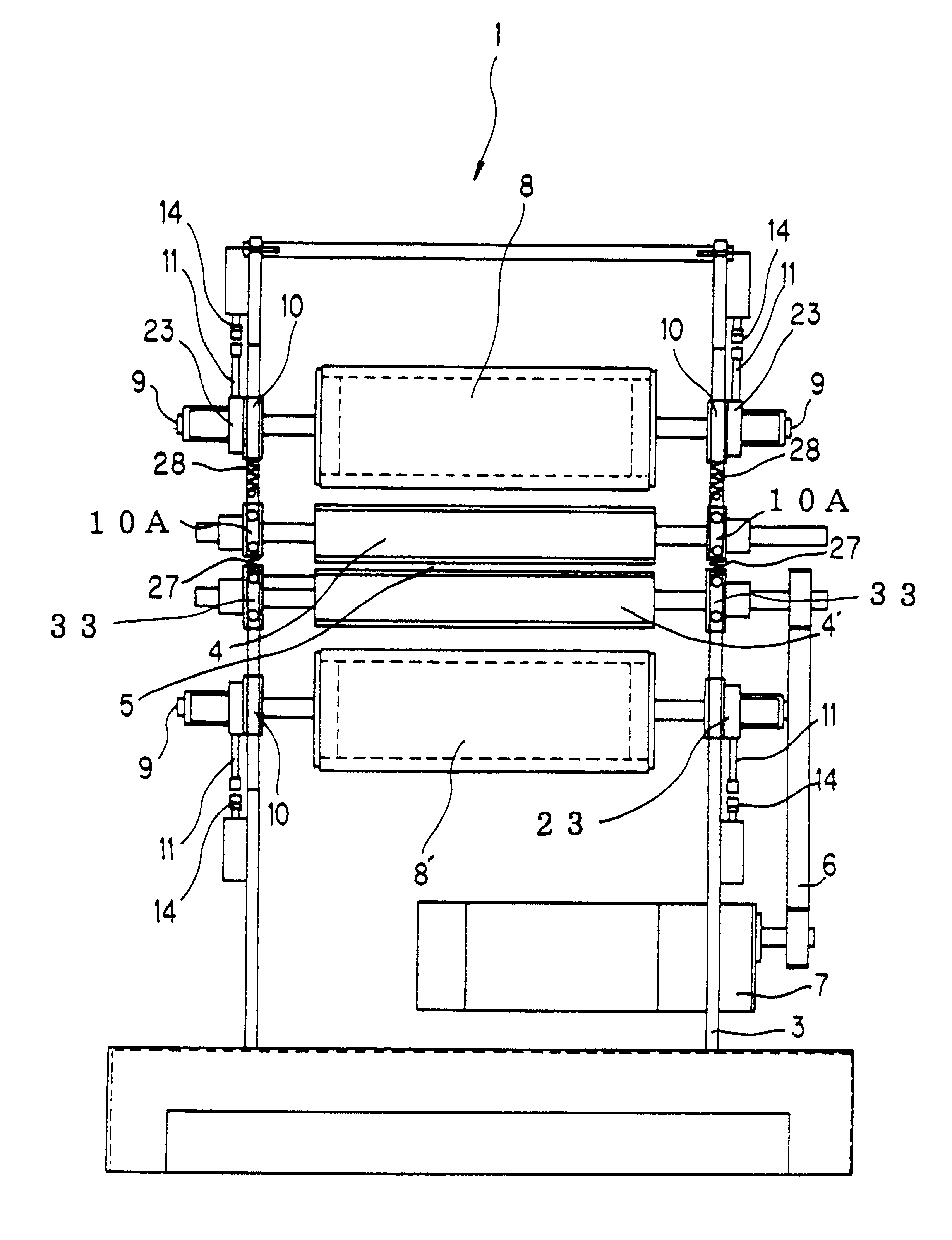
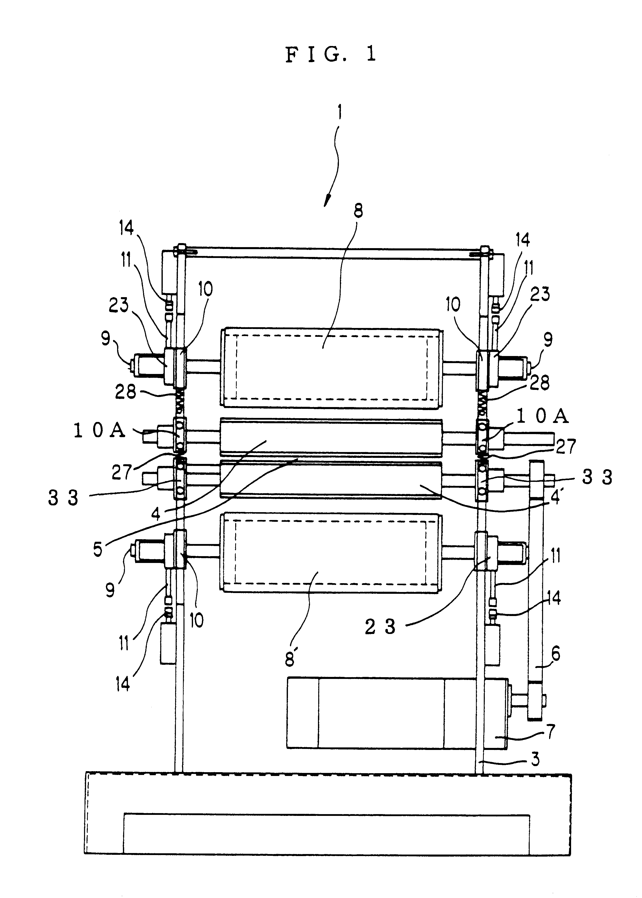
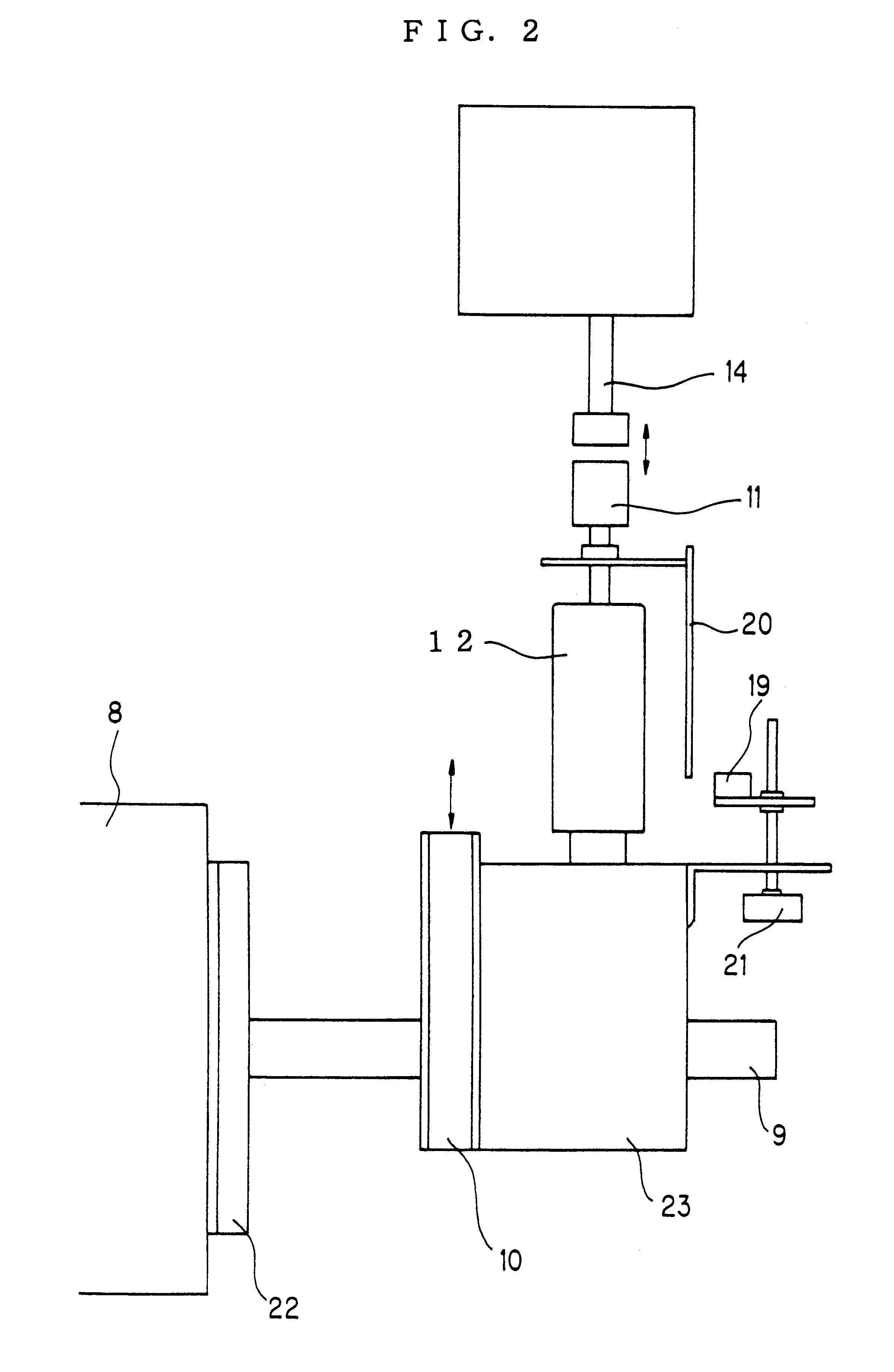
As the substrate or sheet surface cleaning apparatus 1 is provided with the above-described construction, the upper adhesive tape roll 8 is separated from the upper tacky rubber roller 4 in the beginning. When the upper pressing control mechanisms are actuated, the respective pressing rods 14,14 are brought into contact with the pressed rods 11, which are resiliently supported under expansion forces of the compression springs 13,13 in the corresponding pressed rod holders 12,12, and downwardly urge the pressed rods 11,11 while performing positional adjustment by means of the photoreflective sensor 19. As a result, the corresponding slidable bearings 10,10 precisely slide in the downward direction. Therefore, the upper adhesive tape roll 8 integrally supported on these slidable bearings 10,10 via the shafts 9,9 is brought into close contact with the upper tacky rubber roller 4 and downwardly urges the upper tacky rubber roller 4. The upper tacky rubber roller 4 supported on the slid...

second embodiment

As the substrate or sheet surface cleaning apparatus 51 according to the present invention is constructed as described above, the pressure to the substrate or sheet 2 as a material under treatment is maintained constant by the pressing control mechanisms arranged inside the cleaning apparatus 51. The substrate or sheet 2 with dirt or particles deposited on the surfaces thereof is therefore allowed to pass while being held under constant pressure between the tacky rubber rollers 4,4' the surfaces of which are always kept clean by their corresponding adhesive tape rolls 8,8', so that the dirt or particles are surely captured and removed onto the surfaces of the tacky rubber rollers 4,4'.

If the substrate or sheet 2 passes through the space 5 between the tacky rubber rollers 4,4' with its position extremely shifted either leftward or rightward relative to its advancing direction and especially when the substrate or sheet has a large thickness in the above situation, the upper tacky rubb...


PUM


Abstract

A substrate or sheet surface cleaning apparatus is provided with at least one tacky rubber roller and at least one adhesive tape roll which is brought into close contact with the tacky rubber roller. The roller and roll are rotatably supported at opposite ends of their shafts by bearings which are slidable in a vertical direction. Pressed rods are arranged integrally on the slidable bearings for the roll. By urging the pressed rods with pressing rods driven by d.c. motors via gear trains while controlling the d.c. motors by a position sensor, the pressure between the roll and the roller and the pressure between the roller and the substrate or sheet are optimized so that dirt or particles can be efficiently removed from an opposing surface of the substrate or sheet. Another substrate or sheet surface cleaning apparatus is provided two tacky rubber rollers arranged in an up-and-down parallel relationship and two adhesive tape rolls arranged above the upper roller and below the lower roller, respectively. Position adjusters with one or more springs disposed therein are arranged between slidable bearings supporting the upper roller and fixed bearings supporting the lower roller to correct tilting, if any, of the upper roller.

Description

a) Field of the InventionThis invention relates to a cleaning apparatus for removing dirt or particles from at least one surface of a substrate or sheet, on which the dirt or particles have deposited in a fabrication process thereof, by capturing the dirt or particles on a tacky rubber roller having tackiness and then transferring the dirt or particles onto an adhesive tape roll, and especially to a pressing control mechanism for the tacky rubber roller and adhesive tape roll, said pressing control mechanism being useful in the cleaning apparatus. This invention is also concerned with a substrate or sheet surface cleaning apparatus in which a tacky rubber roller can be assured to always remain at a surface thereof in close contact with a surface of substrate or sheet irrespective of the passing state, thickness or the like of the substrate or sheet.b) Description of the Related ArtA substrate or sheet surface cleaning apparatus is provided with a tacky rubber roller having tackiness...

Claims


Application Information

Patent Timeline
Patent Type & Authority Patents(United States)
IPC IPC(8): B08B7/00H05K3/26
CPCB08B7/0028H05K3/26
Inventor EGOSHI, KENTAROMARIYAMA, SHOUHEI
Owner RAYON IND
Why Eureka
Try Eureka