Ion assisted deposition source

a technology of assisted deposition and ion, which is applied in the direction of electrolysis components, vacuum evaporation coatings, coatings, etc., can solve the problems of large volume, high cost, and large equipment, and reduce the overall gas flow required, reduce the vacuum pumping requirement, and minimize the damage to the deposited film

Inactive Publication Date: 2001-05-29
KAUFMAN & ROBINSON
View PDF3 Cites 48 Cited by
  • Summary
  • Abstract
  • Description
  • Claims
  • Application Information

AI Technical Summary

Benefits of technology

Still another object of the present invention is to provide an ion beam for the ion assist function with ions of less than 200 eV / ion to minimize damage to the deposited film.
Yet another object of the present invention is to provide an apparatus that reduces the overall gas flow required and thereby reduces the vacuum pumping requirement.
A more specific object of the present invention is to avoid any need for a dielectric window that can be rendered inoperative by being covered with sputtered material.
A further specific object of the present invention is to avoid any need for a large electromagnet.
Yet another specific object of the present invention is to avoid the production of macroparticles that can degrade the quality of thin films.
In accordance with one specific embodiment of the present invention, the ion assisted deposition source comprises a discharge region into which an ionizable gas is introduced, a sputter target at one end of that region, an axially symmetric field within and extending out the opposite and open end of that region, an anode around the circumference of that region, and an electron emitting cathode located near the open end of that region. Particles are sputtered from the sputter target, pass through the discharge region, and are deposited on a deposition substrate located exterior of both the discharge region and the deposition source. A beam of energetic ions from the discharge region bombards the film being deposited to improve the adhesion, density, and other properties of that film. Some of these ions consist of sputtered particles that have become ionized while passing through the discharge region. There are additional interactions to consider in controlling the deposition source, but the density of the plasma in the discharge region can be controlled with the level of emission from the electron emitting cathode, the emission of sputtered particles from the sputter target can be controlled with the negative potential of that target, while the energy of the ions used to assist in the deposition can be controlled with the positive potential of the anode. The deposition source thus simultaneously generates a flux of sputtered material with which to deposit a film on a substrate and a beam of energetic ions to assist in that deposition, and does so with a simple and economical apparatus. Further, the current and energy of ions in the ion beam are adjustable relative to the flux of sputtered material, so as to provide a wide range of property modifications in the deposited film. It is therefore possible to bombard the deposition surface prior to, during, or after deposition.

Problems solved by technology

A gas supply to the entire evacuated volume is generally associated with excessive pressure at the deposition substrate and therefore contamination of the deposited film.
Using separate devices for the separate deposition and ion assist functions can result in bulky, complicated, and expensive apparatus, as well as excessive total gas flow.
In the case of a cathodic arc, although several functions are included in the cathodic-arc apparatus, the overall apparatus is complicated and expensive.
In the case of a magnetron, the higher background pressure required for its operation increases the likelihood of contamination being included in the film being deposited.
The resulting apparatus, however, is bulky, complicated, and expensive.

Method used


Image

  • Ion assisted deposition source
  • Ion assisted deposition source
  • Ion assisted deposition source

Examples


specific example

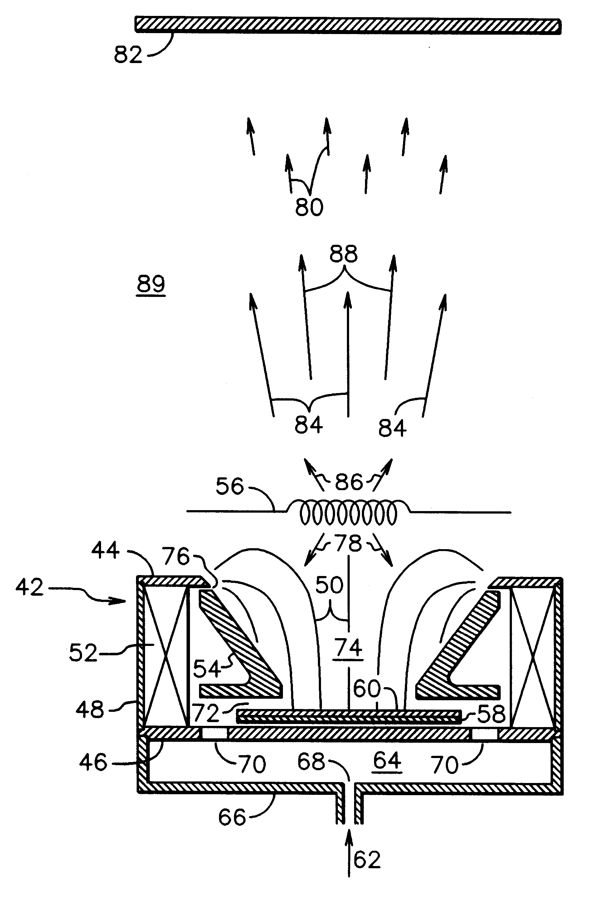
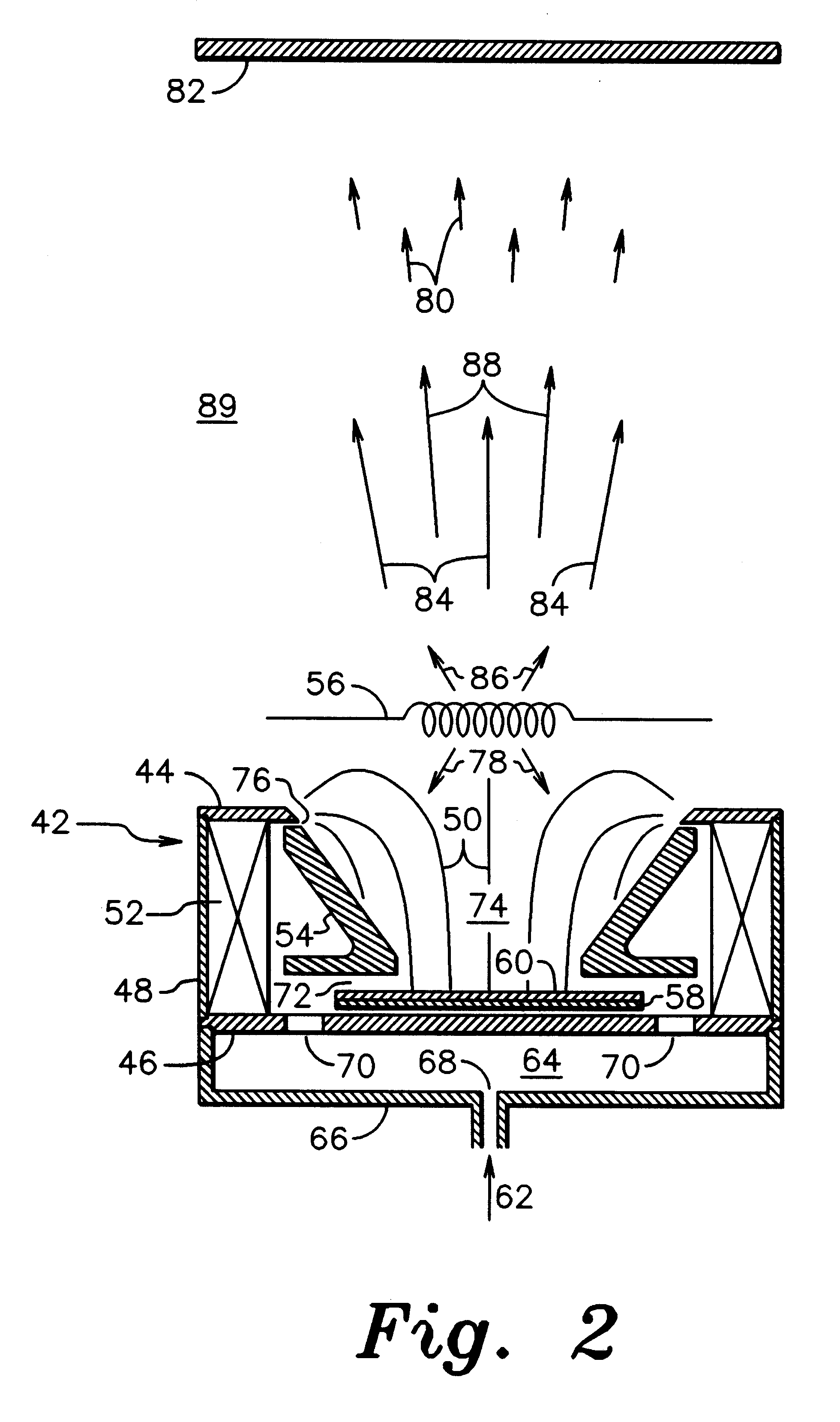
As a specific example of operation, a configuration similar to that shown in FIG. 2 was operated with an inner diameter of the outer pole piece of 38 mm, a separation of inner and outer pole pieces of 39 mm, an anode height of 28.5 mm, an inner anode diameter of 38 mm, and a copper target and its support that together were 3 mm thick and spaced 1 mm from the inner pole piece. The spacing between the anode and the outer pole piece was 1 mm or less. The cathode was a tungsten filament located 12 mm beyond the outer pole piece and with a diameter of 0.51 mm. The heating current to the filament was approximately 20 amperes. With a magnetic field strength at a location both on axis and adjacent to the inner pole piece of 240 Gauss (2.4.times.10.sup.-2 Tesla), a discharge voltage of 60 volts, a discharge current of 2 amperes, and a direct-current target bias of -250 volts, at an argon flow of 42.5 standard cubic centimeters per minute and a background pressure of 4.6.times.10.sup.-4 Torr ...


PUM

PropertyMeasurementUnit
energyaaaaaaaaaa
magnetic fieldaaaaaaaaaa
voltageaaaaaaaaaa

Abstract

In accordance with one specific embodiment of the present invention, the ion assisted deposition source for thin films comprises an axially symmetric discharge region into which an ionizable gas is introduced, a sputter target at one end of that region, an axially symmetric magnetic field within and extending out the opposite and open end of that region, an anode around the circumference of that region, and an electron emitting cathode located near the open end of that region. Particles are sputtered from the sputter target, pass through the discharge region, and are deposited on a deposition substrate located exterior of both the discharge region and the deposition source. A beam of energetic ions from the discharge region bombards the film being deposited to improve the adhesion, density, and other properties of that film. The density of the plasma can be controlled with the emission from the cathode, the emission of sputtered particles from the sputter target can be controlled with the negative potential of that target, while the energy of the ions used to assist in the deposition can be controlled with the positive potential of the anode. The deposition source thus simultaneously generates a flux of sputtered material with which to deposit a film on a substrate and a beam of energetic ions to assist in that deposition, and does so with a simple and economical apparatus.

Description

This invention relates generally to the deposition of thin films, and more particularly to the enhanced properties obtained by the bombardment of the deposition surface with energetic ions before, during, or after the deposition. This process is also known as ion assisted deposition.This invention can be utilized in a variety of thin film applications such as the deposition of decorative or protective films, the deposition of films with specific refractive indexes for optical applications, the deposition of conducting films for solid state electronics, or the deposition of magnetic films for recording heads or recording media.The ion assisted deposition of a thin film has been recognized as a means of improving or controlling a variety of thin film properties such as adhesion, density, stress, or even the selection of a preferred form of molecular bonds as in the deposition of diamondlike carbon. Some examples of ion assisted deposition are described in an article by Harper, et al. ...

Claims


Application Information

Patent Timeline
Patent Type & Authority Patents(United States)
IPC IPC(8): C23C14/35H01J37/32H01J37/34
CPCC23C14/228C23C14/355H01J37/3402H01J37/3438
Inventor KAHN, JAMES R.ZHURIN, VIACHESLAV V.
Owner KAUFMAN & ROBINSON
Why Eureka
Try Eureka