Electrophotographic display device and driving method therefor

Inactive Publication Date: 2001-05-29
CANON KK
View PDF9 Cites 210 Cited by
  • Summary
  • Abstract
  • Description
  • Claims
  • Application Information

AI Technical Summary

Problems solved by technology

However, such liquid crystal display devices are still accompanied with problems of visual load on human eyes, such as difficulty of recognizing characters on display depending on a viewing angle or due to reflection light, and flickering and low luminance of light sources.
Such a conventional electrophoretic display device as described with reference to FIGS. 8A and 8B, however, involves the following problems.
Accordingly, In order to retain a display state, it is necessary to continually apply the voltage to the electrodes, thus requiring a substantial power consumption therefor.
Accordingly, it is difficult to compose the insulating liquid of a single component, so that some coloring particles have to be dispersed or some colorant has to be dissolved in the insulating liquid.
Further, the reflectance of the display is liable to be lowered due to adsorption o

Method used


Image

  • Electrophotographic display device and driving method therefor
  • Electrophotographic display device and driving method therefor
  • Electrophotographic display device and driving method therefor

Examples


example 1

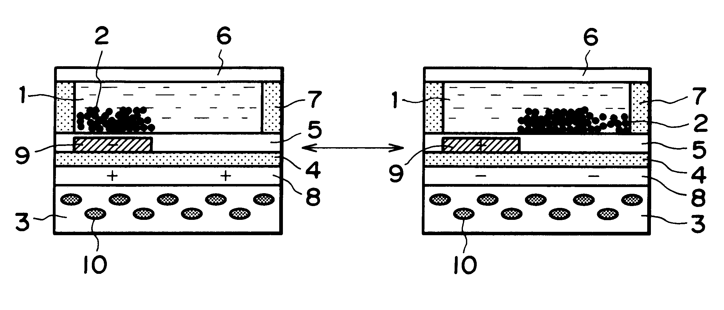
A display device having a matrix of pixels (cells) arranged in 450 rows.times.450 columns was prepared in a planar size of 75 mm.times.75 mm. The display device had a unit cell (pixel structure having planar size of 120 .mu.m.times.120 .mu.m as illustrated in FIGS. 1A and 1B and was prepared in the following manner with reference to FIGS. 4A-4E illustrating production of one unit cell size.

Ferromagnetic cobalt-samarium alloy fine powder 10 was kneaded with melted PET (polyethylene terephthalate) to form a 200 .mu.m-thick film, which was magnetized to provide a first substrate 3 (FIG. 4A) in an entire planar size of 75 mm.times.75 mm.

Then, the first substrate 3 was surface-coated by sputtering with a 200 nm-thick aluminum (Al) film which was then patterned into 120 .mu.m-wide stripes of first electrodes 8. Then, the first electrodes 8 were coated with a 3 .mu.m-thick first insulating layer 4 of PMMA (polymethyl methacrylate) colored in white with titanium oxide fine particles (FIG. 4...

example 2

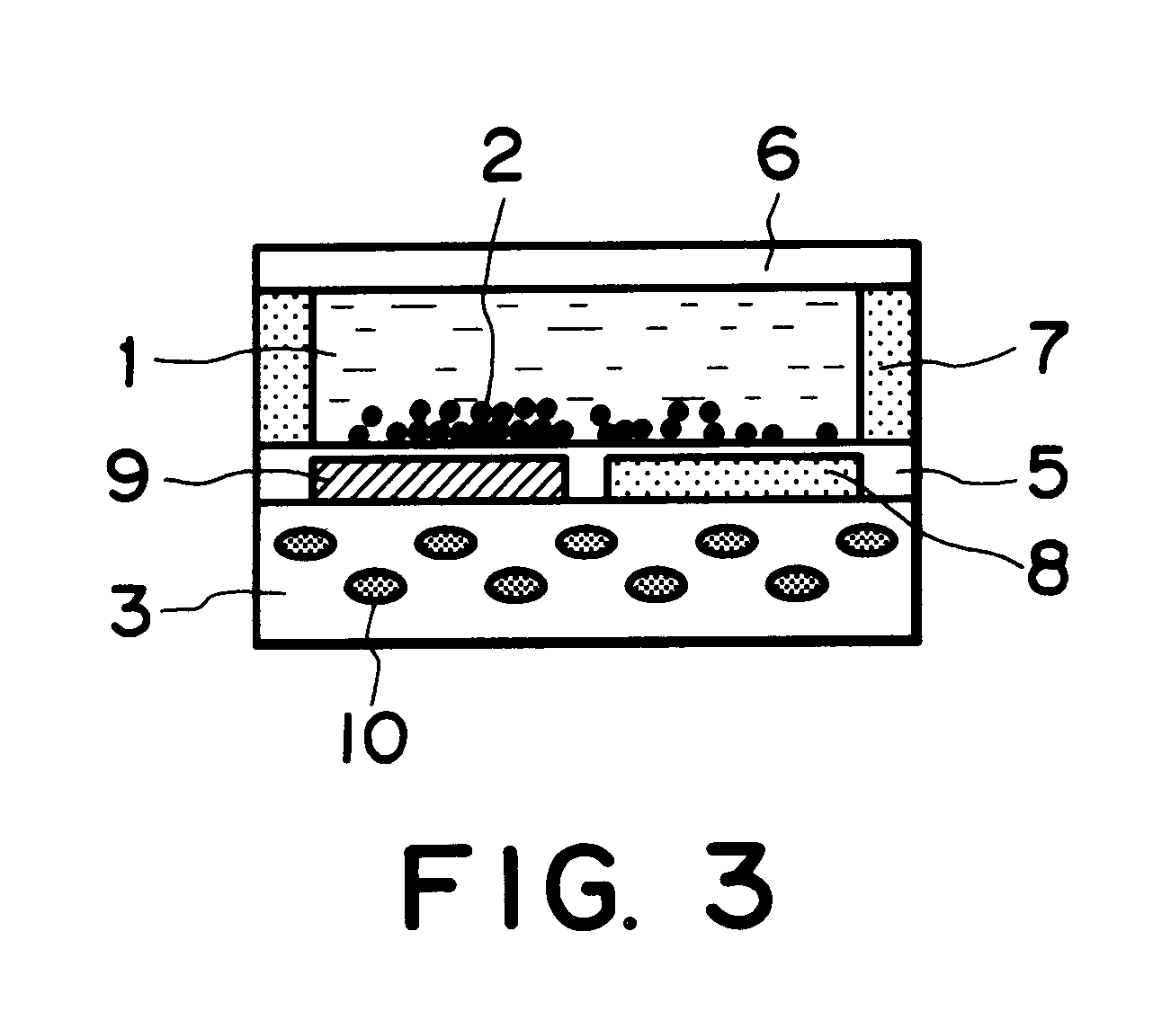
A display device of 450.times.450 pixels similar to the one of Example 1 except for a unit cell structure of 120 .mu.m.times.120 .mu.m as illustrated in FIG. 3 was prepared in a manner described below with reference to FIGS. 5A-5E similarly as in Example 1.

Ferromagnetic alnico fine powder 1 was mixed with polyimide varnish, and the resultant paint was applied onto a 100 .mu.m-thick PES film 3 and baked to form a magnetic layer 51, which was then magnetized (FIG. 5A).

Then, the first electrode 3 provided with the magnetic layer 51 was coated with an Al film, followed by patterning to provide first electrodes 8, and then with a white first insulating layer 4 of polyimide colored in white by inclusion of titanium oxide fine particles (FIG. 5B).

Then, a dark black-colored titanium carbide film was formed on the insulating layer 4 and patterned by photolithography including dry etching into 30 .mu.m-wide stripes of second electrodes 9. Then, in parallel with the stripes of second electrode...

example 3

The display device prepared in Example 1 was driven for gradational display in the following manner.

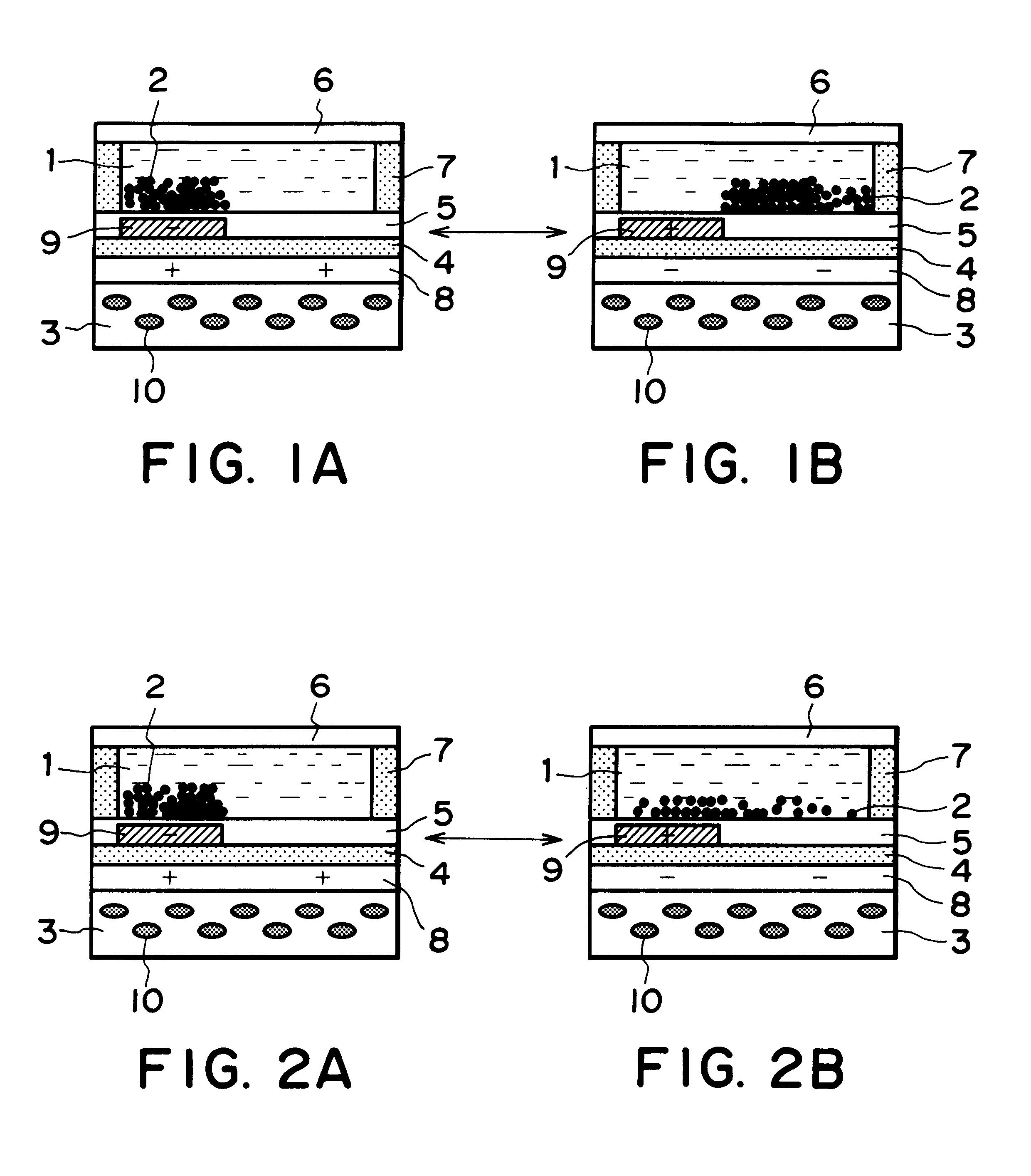
First, similarly as in Example 1, when the second electrode 9 was supplied with +80 volts for 30 msec. while the first electrode 8 was grounded (0 volt), the positively charged electrophoretic particles 2 were moved to mask the white first insulating layer 4 on the first electrode 8, thereby providing a black display state as viewed from the side of the second substrate 6 (FIG. 1B).

Then, when the first electrode 8 was supplied with +80 volts for 30 msec while the second electrode 9 was grounded, the positively charged electrophoretic particles 2 were moved onto the second electrode 9 to expose the while color of the first insulating layer 4 thereby providing a slightly grayish white display state (FIG. 2A).

Then, again from the state shown in FIG. 1B, the first electrode 8 was supplied with +80 volts for 5 msec instead of 30 msec while the second electrode 9 was grounded, whereby a por...


PUM


Abstract

An electrophoretic display device exhibiting a memory characteristic, i.e., capable of holding a display state even after removal of an applied voltage, is provided by introducing a mechanism that colored electrophoretic particles are retained in position for display in the absence of an electric field. For the purpose, at least one of a pair of substrates holding therebetween colored electrophoretic particles together with an insulating liquid is provided with a magnetism by disposing a magnetic material on or in the substrate together with the use of magnetized colored electrophoretic particles so as to retain the colored electrophoretic particles in position under the action of a magnetic Coulomb force exerted by the magnetized substrate.

Description

FIELD OF THE INVENTION AND RELATED ARTThe present invention relates to an electrophoretic display device wherein colored electrophoretic particles or charged migrating particles are moved to effect a display, and a driving method thereforIn recent years, accompanying the progress of data processing apparatus, there has been an increasing demand for a display device requiring a small power consumption and a small thickness, and extensive study and development have been made on devices satisfying such a demand. Among these, a liquid crystal display device wherein an alignment of liquid crystal molecules is electrically controlled to change optical characteristics has been extensively developed and commercialized as a display device satisfying the demand described above.However, such liquid crystal display devices are still accompanied with problems of visual load on human eyes, such as difficulty of recognizing characters on display depending on a viewing angle or due to reflection li...

Claims


Application Information

Patent Timeline
IPC IPC(8): G02F1/01G02F1/167G02F1/16755G02F1/1685
CPCG02F1/167G02F1/1685G02F1/16755
Inventor IKEDA, TSUTOMU
Owner CANON KK
Why Eureka
Try Eureka