
Method for detecting power plane-to-power plane shorts and I/O net-to power plane shorts in modules and printed circuit boards

a technology of power planes and modules, applied in the field of detecting power planetopower plane shorts and i/o netto power plane shorts in modules and printed circuit boards, can solve the problems of generic pcb (printed circuit board), shorts between power planes in electronic packages such as mcm-d, and posing several significant yield and diagnostic problems, and achieves low cost and high yield and diagnostic leverage.

Inactive Publication Date: 2001-06-05
IBM CORP
View PDF14 Cites 35 Cited by
  • Summary
  • Abstract
  • Description
  • Claims
  • Application Information

AI Technical Summary

Benefits of technology

It is yet another object of the invention to provide a method and a apparatus to perform a simple test to thousands of I / O nets for detecting shorts between power planes and to provide an apparatus for locating these shorts.
It is still another object of the invention to provide a low cost alternative to supplement expensive equipment commonly required for AOI (Automated Optical Inspection).
It is yet a further object of the invention to provide high yield and diagnostic leverage by targeting selected common classes of fatal short defects, such as power plane shorts or I / O net-to-power plane shorts.

Problems solved by technology

Power plane-to-power plane shorts are a common defect that typically necessitate scrapping an electrical component if they are not detected and repaired during the early stages of manufacturing.
Locating shorts poses several significant yield and diagnostic problems.
Firstly, shorts between power planes in an electronic package such as an MCM-D (multi-chip module provided with thin film layers) or a PCB (printed circuit board) are a generic and perennial problem both for yield and diagnostic considerations.
However, to precisely locate the short is usually a formidable task, since such a defect can appear anywhere in the active area between adjoining power planes.
Additionally, the complex nature of thin-film packaging makes it prohibitively expensive to inspect the entire MCM-D or PCB in order to determine the precise location of a short with a reasonable degree of accuracy.
A second problem involves reliability considerations.
Certain defects may be exceedingly tenuous, such as filamentary shorts which, typically, blow out when traversed by an even minimal current.
Attempting to view such shorts with infrared techniques most likely will blow the short.
A third problem occurs in some shorts having a high resistance, and oftentimes, a significant amount of power plane-to-power plane capacitance.
A fourth problem, involves a specific defect known to be fatal: I / O net-to-power plane shorts.
Repair opportunities for such nets are typically limited.
Moreover, both, electrical test and automated optical inspection techniques tend to be expensive.
TSM metal patterns are extremely dense and expensive to make.
Although detecting this type of defect may appear simple, locating the actual defect may be a formidable task since hundreds of thousands of places in the TSM may exist where two power planes or a power plane to an I / O net can short to each other.
It may be difficult and ineffective to rely on unassisted manual inspection of the entire area.
This approach may subject the fragile electrical component to high current stresses and may lack adequate sensitivity for the more difficult case of finding high resistance power plane-to-power plane shorts.
None of these applications, however, address the special problems and concerns of power plane-to-power plane shorts or high resistance power plane-to-power shorts.
Nor do they address the simplified case of I / O net-to-power plane shorts.
Nor do they separate signals caused by noise or unwanted capacitive effects from the signal due to a power short.
Generally, all the radiated electromagnetic energies sensed with the predetermined signature of the profile are compared, although the electromagnetic sensed energy is not necessarily helpful in locating a power plane-to-power plane short.
It is, therefore, not considered to be helpful, but rather a hinderance.
Furthermore, none are sensitive to weak magnetic signals in combination with noise.
Nor do they address capacitive effects caused by the plane-to-plane capacitance or by the probe-to-the board under test capacitance.
This is not as desirable with regard to sensitivity considerations.
The PCB under test may be limited in the amount of current stress that it can be subjected to.
This does not address power plane-to-power plane shorts which are not a linear net trace nor does it address high resistance shorts.
It uses a simple threshold for detection and will become less effective as noise increases and as the signal decreases.
This method is also not extendable to high resistance shorts.
This approach is limited to locating shorts in electronic packages having dense parallel x,y addressing lines, e.g., LCD, but it does not address locating power plane-to-power plane shorts.
These are not pertinent to locating power plane shorts and do not address the case of locating high resistance shorts between power planes which demands a much higher sensitivity.
The need is not related to detection but rather to the location and inspection of plane-to-plane faults and these methods do not address that necessity.
This method is not extendible to high resistance shorts.
Both Sheen and Khazam require much more complex hardware than is necessary for the narrower case of power plane-to-power plane shorts.
Likewise, Soiferman uses a broad spectrum which is not adequately sensitive to a weak signal buried in noise.
This method will not be extendible to high resistance shorts.

Method used


Image

  • Method for detecting power plane-to-power plane shorts and I/O net-to power plane shorts in modules and printed circuit boards
  • Method for detecting power plane-to-power plane shorts and I/O net-to power plane shorts in modules and printed circuit boards
  • Method for detecting power plane-to-power plane shorts and I/O net-to power plane shorts in modules and printed circuit boards

Examples


Embodiment Construction

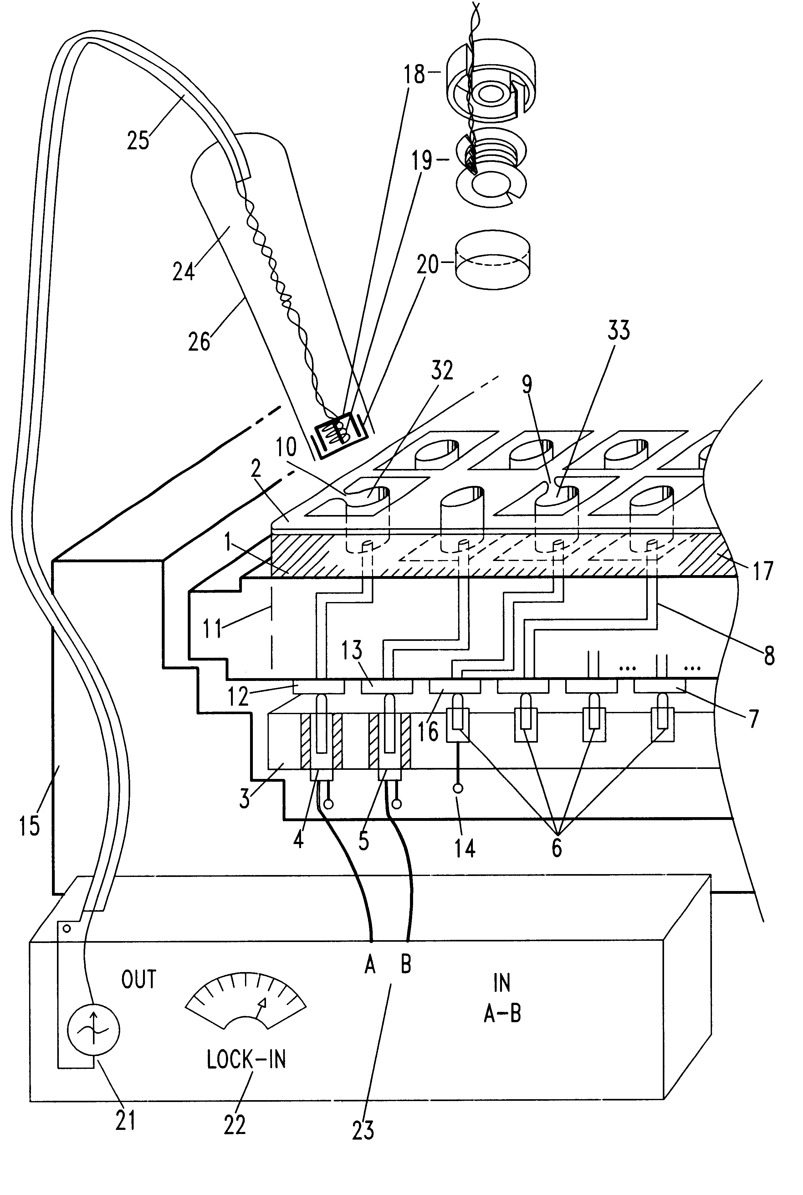
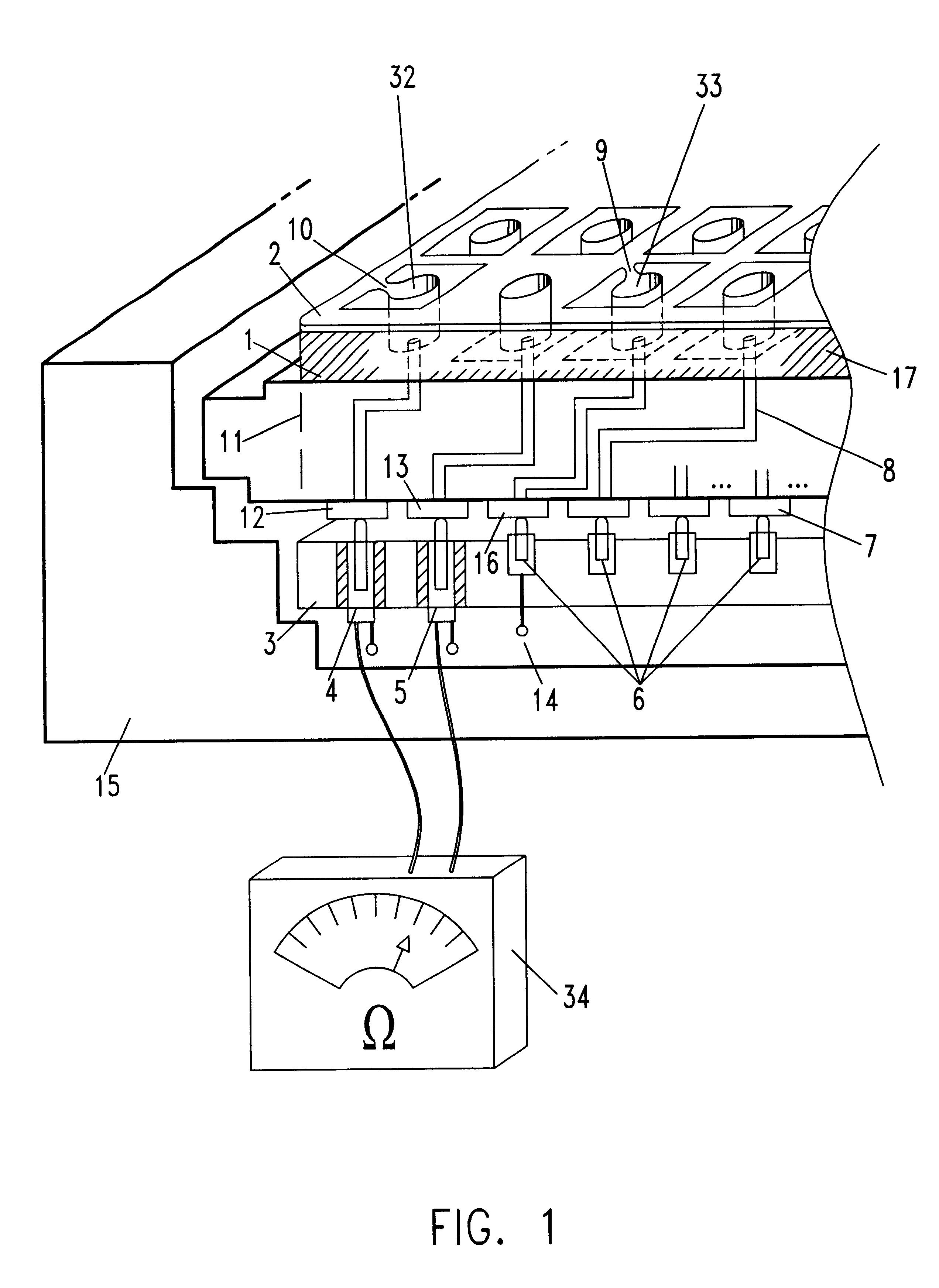
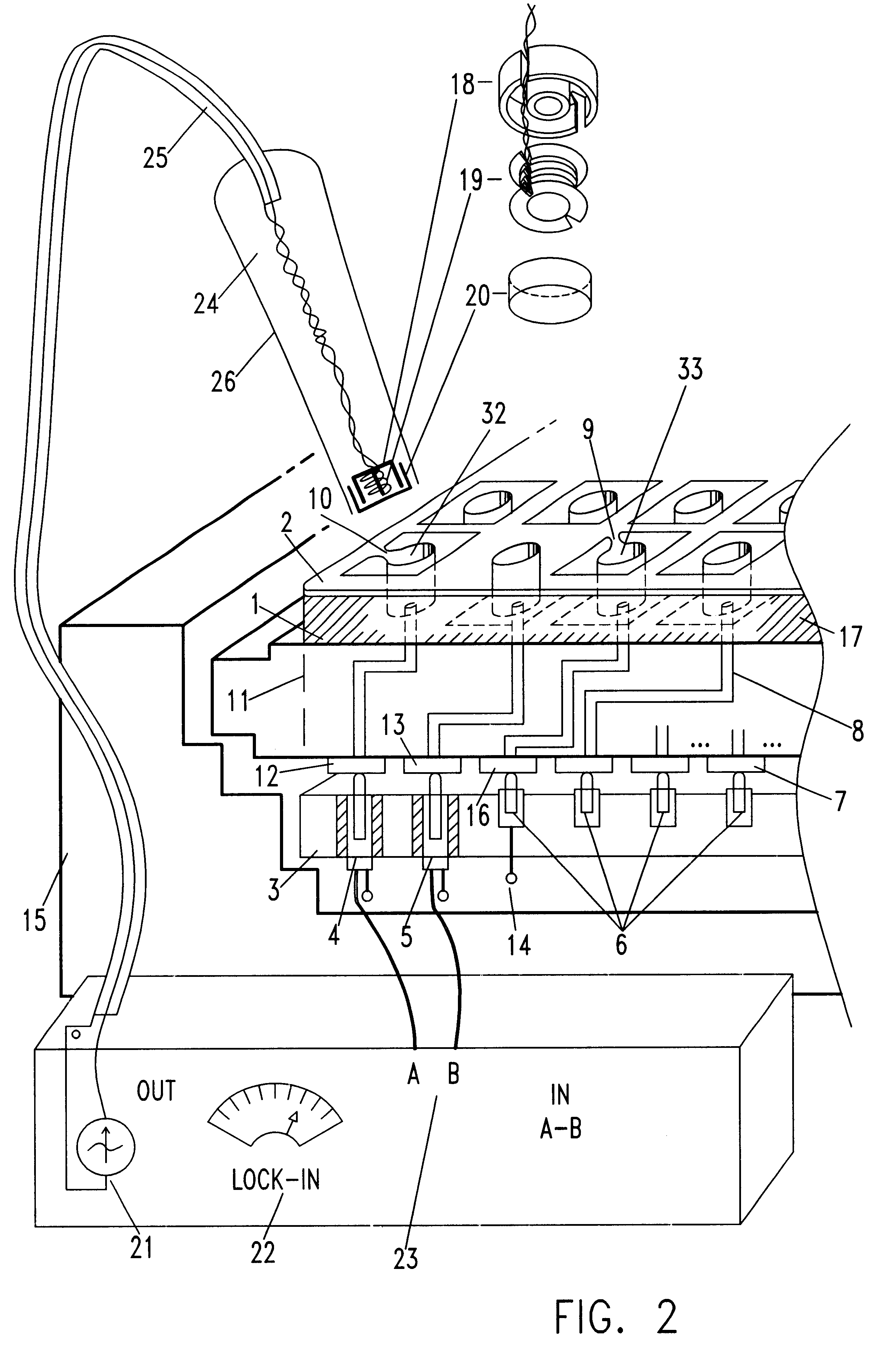
Referring now to FIG. 1, there is shown a schematic diagram of a module or a board (or substrate) showing a short between power planes, and a short between an I / O net and a power plane.

Practitioners of the art will appreciate that I / O nets refer to any and all wiring nets leading to a module or board pin. Hereinafter, they will be referred to I / O nets.

A module or board 11 is mounted on a fixture 15. Bottom surface metallurgy (BSM) pads referenced by numerals 7, 12, 13 and 16, provide connections to the wiring throughout the module or board, as well as to the power planes. Wiring 8 connects the BSM pads to the top surface metallurgy. Voltage BSM pad 12 connects power plane 1 to TSM pad 32. Plane 1 is depicted shorted to plane 2 by way of short 10. Voltage BSM pad 13 is connected to power plane 2. I / O BSM pad 16 is connected internally to TSM pad 33. Power plane 2 is shown shorted to the I / O net associated with TSM pad 33 by way of short 9. Insulation 17 separates the power planes and...


PUM


Abstract

A method of locating in a non-destructive and non-invasive manner power plane-to-power plane shorts or I / O net-to-power plane shorts found in a printed circuit board or a multi-chip-module by way of a magnetic field generating probe is described. Thousands of nets can be simultaneously tested to detect not only the presence of a short but also to accurately pinpoint its position. For high resistance shorts, the probe is provided with a pot core housed inductor located at its tip, and is used at low frequencies to minimize the effect of the capacitive impedance between the power planes. For low resistance shorts, the probe is used at high frequencies, delivering equal but opposite current to each of two matched inductors at the tip of the probe to maximize mutual inductive coupling while minimizing electrostatic capacitive coupling with the board or module. In both cases, the highest current stress is on the probe rather than on the expensive and fragile package under inspection. This allows the test to be both more sensitive to high resistance shorts at low frequencies and is less destructive, thereby being less likely to blow filamentary shorts due to high current stresses through the board or module.

Description

This invention is related to the testing and inspection of multi-chip modules or printed circuit boards and, more particularly, to a method of locating shorts between voltage planes or between I / O nets and power planes for purposes of diagnostics and repair.Power plane-to-power plane shorts are a common defect that typically necessitate scrapping an electrical component if they are not detected and repaired during the early stages of manufacturing. Locating shorts poses several significant yield and diagnostic problems. Firstly, shorts between power planes in an electronic package such as an MCM-D (multi-chip module provided with thin film layers) or a PCB (printed circuit board) are a generic and perennial problem both for yield and diagnostic considerations. Typically, an ohmmeter is used to determine the presence of power plane-to-power plane defects. However, to precisely locate the short is usually a formidable task, since such a defect can appear anywhere in the active area be...

Claims


Application Information

Patent Timeline
IPC IPC(8): G01R31/28G01R1/073G01R31/02
CPCG01R31/281G01R1/07314G01R31/025G01R31/52
Inventor SCAMAN, MICHAEL E.YARMCHUK, EDWARD J.HALPERIN, ARNOLD
Owner IBM CORP
Learn More