Solder joint reliability

a technology of solder joints and reliability, applied in the field of solder joints, can solve the problems of reducing the resistance to solder joint fatigue failure, adding to time and cost of manufacture, and difficult to align small solder joints during re-flow in manufacture, so as to improve the reliability of solder joints and improve the alignment of such joints

Inactive Publication Date: 2001-06-12
HANGER SOLUTIONS LLC +1
View PDF5 Cites 31 Cited by
  • Summary
  • Abstract
  • Description
  • Claims
  • Application Information

AI Technical Summary

Benefits of technology

The invention seeks to provide a method for improving the reliability of solder joints for electrical components having high frequency interconnections and for improving the alignment of such joints during manufacture.

Problems solved by technology

Such fatigue is caused by thermal expansion mismatch between the component and the circuit board.
Use of smaller solder joints, whilst advantageous with respect to electrical conductivity for high frequency signals, has the disadvantage that resistance to solder joint fatigue failure may be reduced.
It is also difficult to align small solder joints during re-flow in manufacture.
This results in additional production processes--underfill dispensing and curing, either by heating or by ultra-violet irradiation--adding to time and cost of manufacture.
The use of epoxy underfill also makes subsequent re-work more difficult and, in particular, precludes simple re-soldering.

Method used


Image

  • Solder joint reliability
  • Solder joint reliability
  • Solder joint reliability

Examples


Embodiment Construction

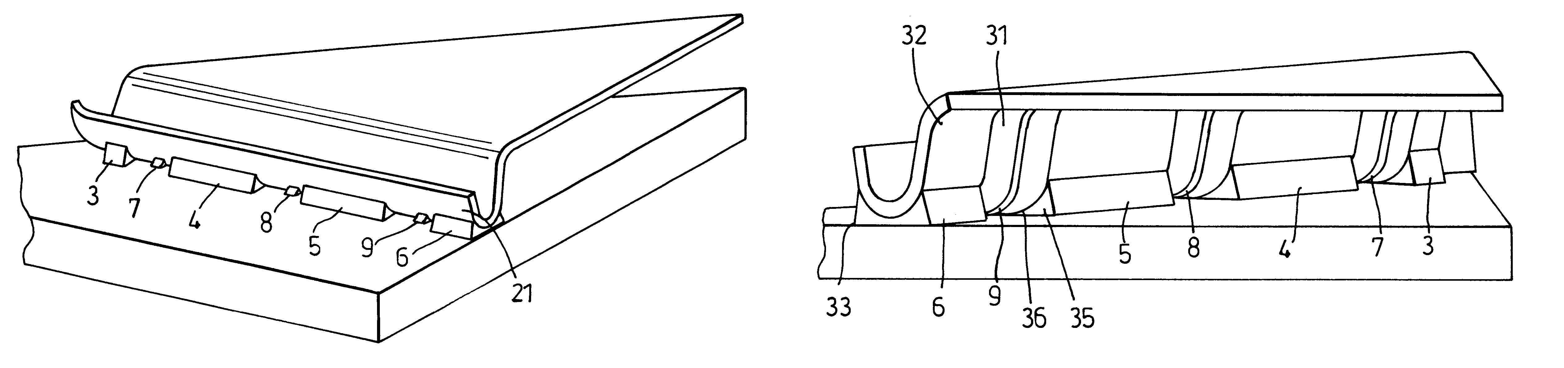
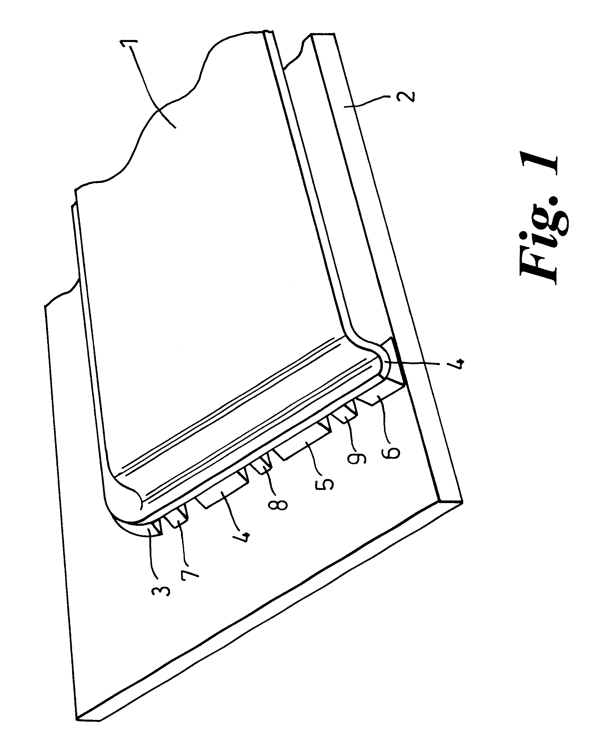
FIG. 1 shows a cut-away view of a surface-mount peripheral package 1 attached around its rim 11 to a printed wiring board (PWB) 2 (or circuit board) by means of a plurality of solder joints 3-9.

The solder joints, in addition to providing the physical attachment of package to board, form electrical connections between a first circuit portion located on the underside of the package and a second circuit portion located on the circuit board surface. Electrical connection may also be provided between the outer surface of the package and the circuit board for the purpose of providing electrical grounding whereby to provide electromagnetic shielding of the circuit enclosed by the package.

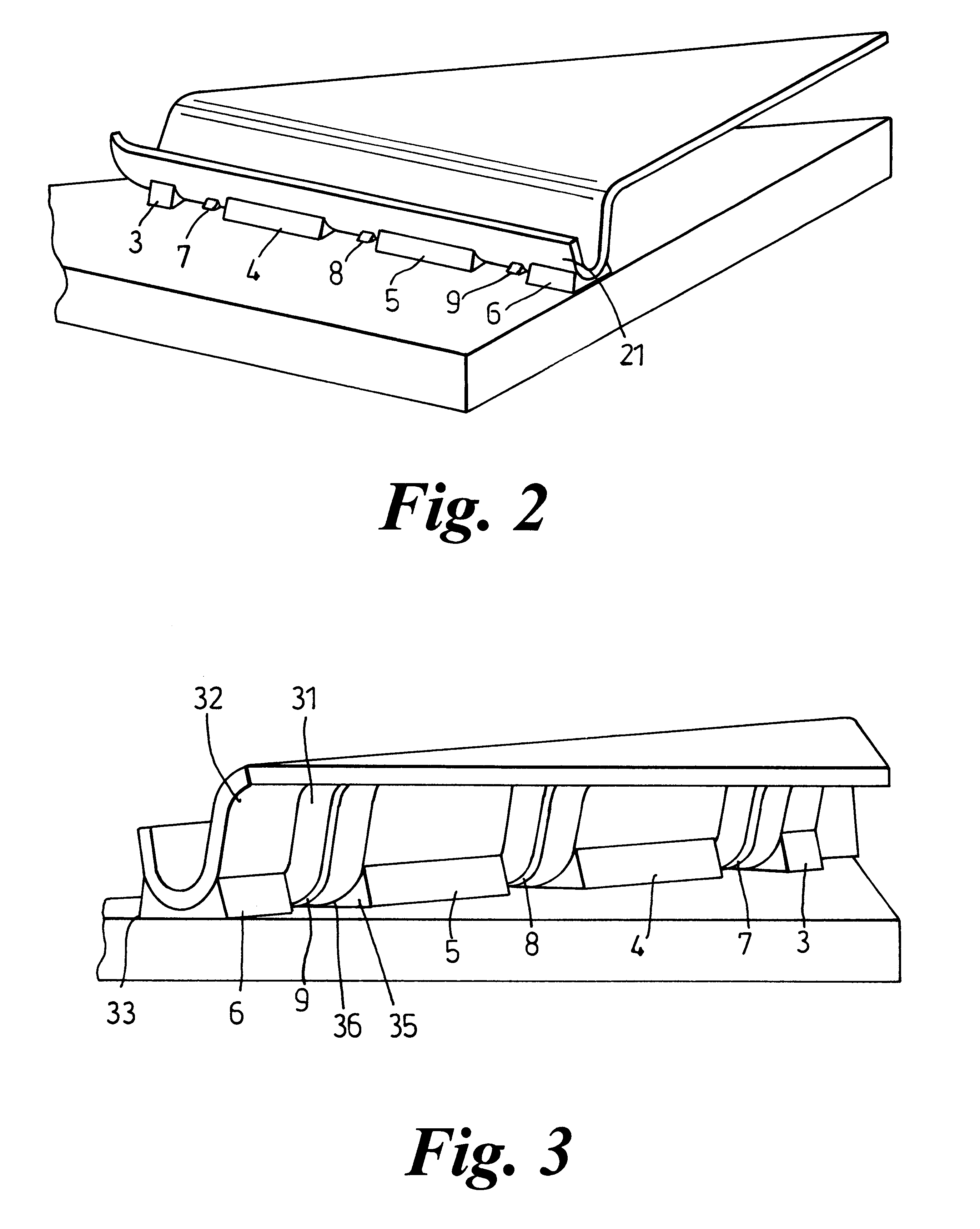
Referring now to FIGS. 2 and 3, there are shown views of a portion of the arrangement shown in FIG. 1, comprising a one eighth portion of the peripheral package. In each case a perspective view is shown, revealing the outer face 21 and inner face 31 of the rim 11 of the package respectively. Seven solder j...


PUM


Abstract

An electrical circuit arrangement comprising a circuit board and an electrical component attached thereto by a plurality of solder joints. The sizes of the joints are chosen according to a characteristic (for example the frequency) of signals to be conducted through them. The joint sizes are inversely proportional to the frequency of signals which they are arranged to conduct. The expected fatigue life of the arrangement is greater than one in which all joints are of a smaller size, as required for example for high frequency signals, and this reduces the need for component underfill.

Description

The present invention relates to a method for improving electrical equipment reliability by use of improved solder jointing techniques.BACKGROUND TO THE INVENTIONSolder joints serve three functions: physical attachment of electronic components (for example peripheral packages) to a circuit board, completion of an electrically conductive path from the circuit component to the board, and provision of a thermally conductive path between the electronic component and the board. These functions may have conflicting requirements.For physical attachment of electronic components it is typically the case that longer fatigue life may be achieved by use of larger solder joints. Such fatigue is caused by thermal expansion mismatch between the component and the circuit board. Similarly, larger solder joints typically improve thermal conductivity between component and board.Use of smaller solder joints, whilst advantageous with respect to electrical conductivity for high frequency signals, has the...

Claims


Application Information

Patent Timeline
Patent Type & Authority Patents(United States)
IPC IPC(8): H05K1/02H05K3/34H05K3/36
CPCH05K1/0243H05K1/0219H05K3/3421H05K3/363H05K2201/09236H05K2201/094H05K2201/10689H05K2201/10734
Inventor ABRAHAM, IAN ANDREWLIU, ANDREW SIU HING
Owner HANGER SOLUTIONS LLC
Why Eureka
Try Eureka