Electro-optical reconnaissance system with forward motion compensation

a technology of forward motion compensation and optical reconnaissance system, which is applied in the field of optical reconnaissance system with forward motion compensation, can solve the problems of insufficient image motion compensation techniques to provide image motion compensation, limited frame size and resolution, and due to blurred images

Inactive Publication Date: 2001-07-03
BAE SYST INFORMATION & ELECTRONICS SYST INTERGRATION INC
View PDF22 Cites 147 Cited by
  • Summary
  • Abstract
  • Description
  • Claims
  • Application Information

AI Technical Summary

Problems solved by technology

One of the more frequently encountered problems in designing aerial reconnaissance imaging systems is determining the most effective method of compensating for image smear or blurring.
Typically, smearing occurs when low ambient light conditions prevent an imaging system from using sufficiently short exposure times, resulting in a blurred image due to the forward motion of the aircraft.
However, these aforementioned image motion compensation techniques are inadequate to provide for image motion compensation in each of the various mission scenarios described above.
Up until recently, frame size and resolution were limited, due to the size and fewer number of pixels in staring arrays.
Until recently, EO framing cameras were not operationally viable due to their small image area and technology limitations associated with data processing and storage.
Additionally, these methods are contrasted with an uncompensated imager.
Image smear causes a loss of image quality as a function of its magnitude.
While average FMC imagers provide average FMC correction, they do not compensate for the different magnitudes of the image vectors at different distances from the flight path.
Therefore, unless the image motions are uniform, even with a perfect match to the desired average charge / image velocity, certain columns would exhibit lead or lag smear errors.
Even though these errors are much less than for the uncompensated imager, these errors result in less than optimum performance.
In the side oblique image collection mode, compensation of the image motion is complex.
In addition to adding greatly to the complexity of the chip drive electronics, the added complexity of the detector chip makes it difficult, expensive, and risky to produce.
These same factors tend to limit the ultimate size (i.e., pixel count) of a column-segmented imaging device.
Without a focal plane shutter in place, this charge motion rate might be correct for one column or small group of columns, but would be incorrect for all other column groups.
However, the complexities of multiple vertical clocks and potentially low yield CCD architecture are still present.

Method used


Image

  • Electro-optical reconnaissance system with forward motion compensation
  • Electro-optical reconnaissance system with forward motion compensation
  • Electro-optical reconnaissance system with forward motion compensation

Examples


Embodiment Construction

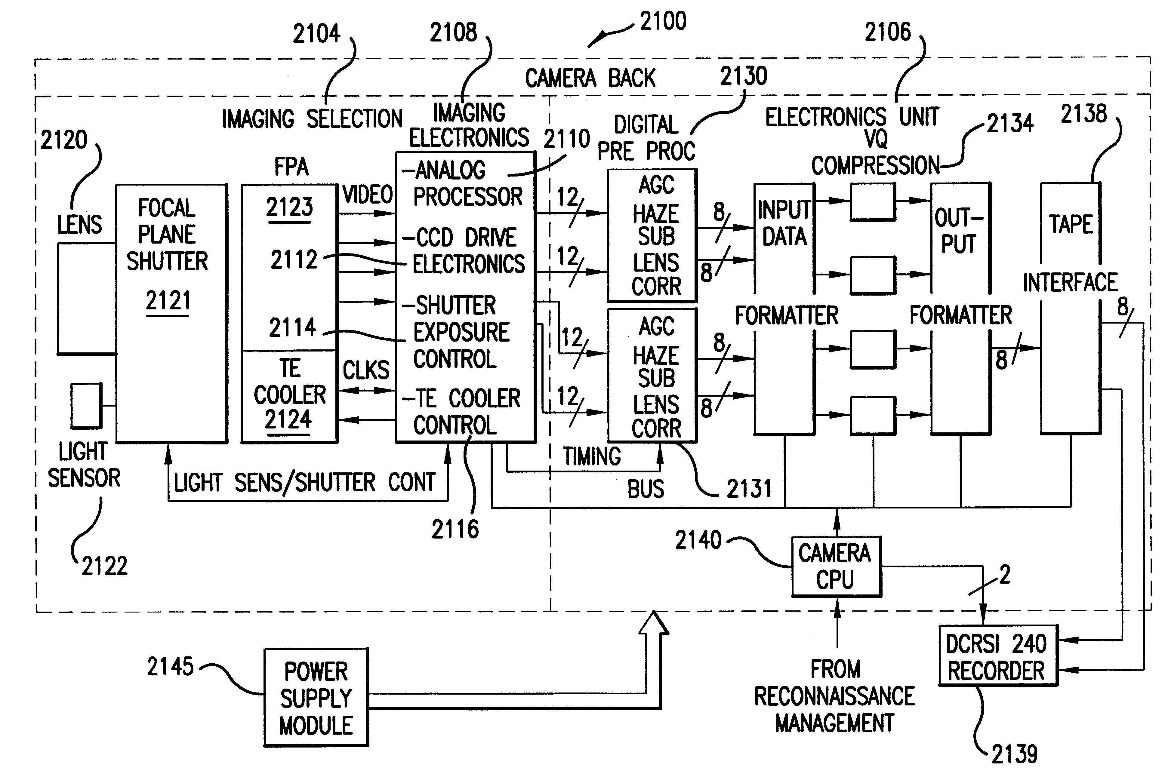
The present invention can be incorporated in numerous different reconnaissance systems using current and yet-to-be-developed cameras, focal planes, and electronics systems adapted to provide a charge transfer rate that is uniform across the CCD and is time-varying in coordination with the focal plane shutter motion. The present invention is designed to utilize a variety of possible focal plane arrays, CCD imaging electronics, and system electronics to meet a specific set of desired performance specifications and parameters of the operating environment (e.g., ambient light conditions, aircraft velocity, altitude, distance to target, etc.). It will be apparent to one skilled in the art that alternative embodiments and structures may be utilized to meet these specifications and parameters. Additionally, these or alternative embodiments and / or structures may be utilized to meet alternative specifications and / or parameters.

a. Focal Plane Array

Although the invention can be utilized with n...


PUM


Abstract

An electro-optical framing camera forward motion compensation (FMC) reconnaissance system comprising a moving shutter and a full frame focal plane array detector is designed to minimize the variation of image motion from a target scene across the focal plane array. The full frame focal plane array, such as a Charge Coupled Device (CCD), is designed to transfer and add the image from pixel to pixel at a predetermined rate of image motion corresponding to the region exposed by the focal plane shutter. The focal plane shutter aperture and velocity are set to predetermined values coordinated with the available illumination. The CCD image transfer rate is set to minimize the smear effects due to image motion in the region of the scene exposed by the focal plane shutter. This rate is variable with line of sight depression angle, aircraft altitude, and aircraft velocity/altitude ratio. Further, a method of FMC utilizes a comparison of a measured light level to a standard value in order to determine the appropriate exposure time and shutter motion rate. An optimal FMC clocking signal is calculated based on image motion equations incorporated in the processing unit of the reconnaissance system.

Description

1. Field of the InventionThis invention relates generally to electro-optical reconnaissance systems whose angular resolution is greater than the product of the exposure time and the angular rate of image motion. The invention is a forward motion compensation (FMC) system that permits full resolution performance when the target line-of-sight-angular-rate-exposure-time product is greater than the angular resolution of the system. The system includes optics, a mechanical shutter and full frame CCD.2. Related ArtAerial reconnaissance systems have undergone a dramatic transition in the past two decades with the replacement of photographic film by electro-optic image sensors. With the advent of wafer-scale focal planes that provide sufficient coverage and resolution, reconnaissance systems are being designed to utilize electro-optic sensors configured as large format area arrays. These electro-optic ("EO") reconnaissance imaging systems most often employ charge-coupled devices ("CCDs") op...

Claims


Application Information

Patent Timeline
Patent Type & Authority Patents(United States)
IPC IPC(8): G01C11/02G01C11/00H04N3/15H04N5/225H04N5/232H04N5/353H04N5/372
CPCG01C11/02H04N5/37206H04N5/372H04N5/353H04N25/53H04N25/711H04N25/71
Inventor MATHEWS, BRUCE ALBERTCOON, BRYAN HUNTINGTON
Owner BAE SYST INFORMATION & ELECTRONICS SYST INTERGRATION INC
Why Eureka
Try Eureka