Scanning apparatus

Inactive Publication Date: 2001-07-10
QINETIQ LTD
View PDF8 Cites 29 Cited by
  • Summary
  • Abstract
  • Description
  • Claims
  • Application Information

AI Technical Summary

Problems solved by technology

This is not possible using existing systems.
At present, large two-dimensional arrays of receivers which cover the whole of a required image are not available.
Ultimately, electronic scanning and staring array techniques could be developed to implement real-time millimetre wave imaging, although there are several problems associated with such a solution.
Secondly, the cost per channel is high so that any electronically scanned or staring array technique is expensive.
Furthermore, in the case of millimetre wave staring arrays there are fundamental problems analogous to the cold shielding problems encountered

Method used


Image

  • Scanning apparatus
  • Scanning apparatus
  • Scanning apparatus

Examples


Embodiment Construction

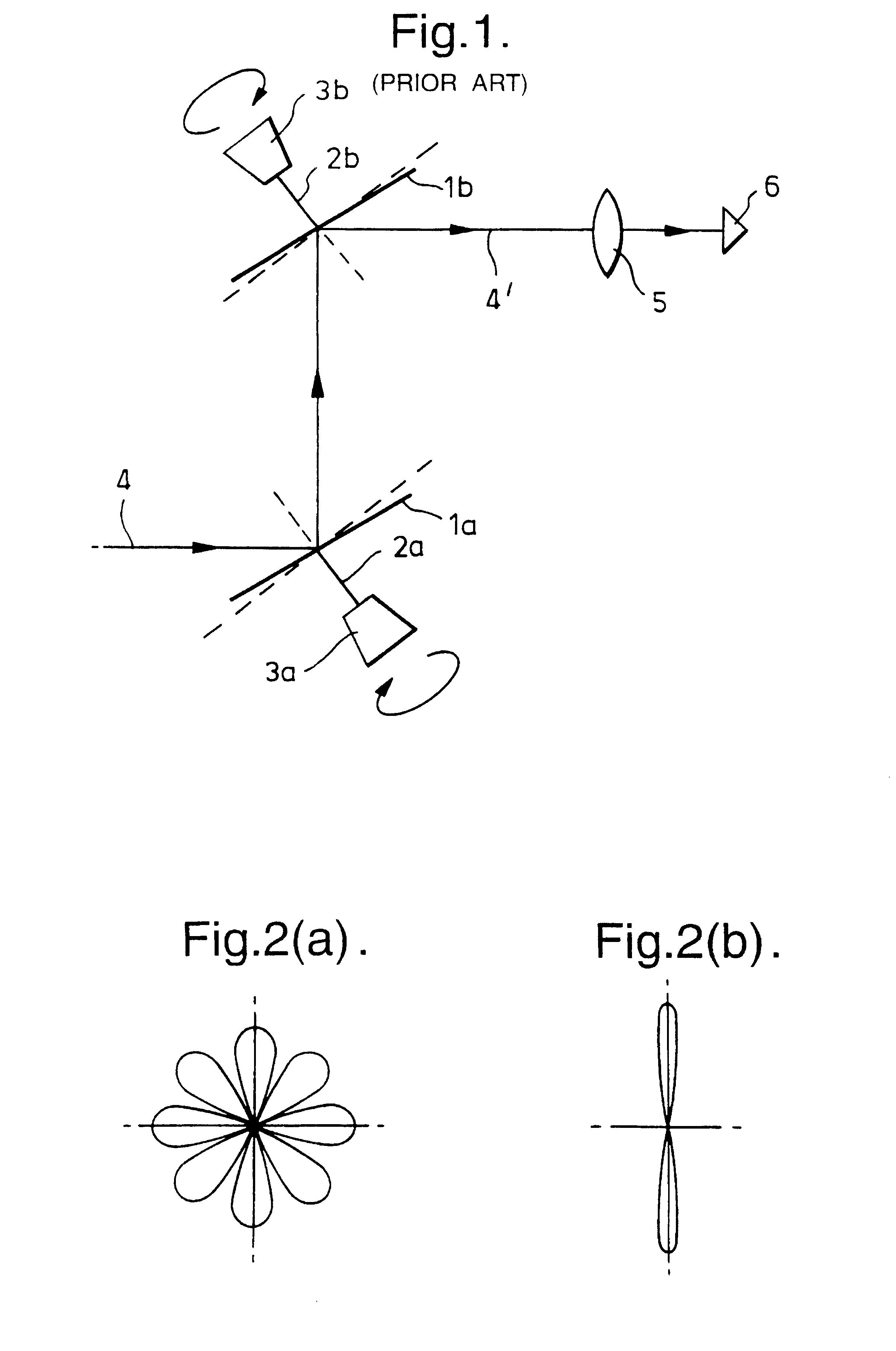
Referring to FIG. 1, a conventional two disc rotating system comprises two discs 1a, 1b, each supported on a separate axis 2a,2b which is connected to a rotor mechanism 3a,3b. Each axis 2a,2b is inclined a few degrees to the normals to the faces of the discs 1a,1b. Typically the angle of inclination is 5.degree.. As the discs 1a, 1b rotate about their respective axes, incident radiation 4 from the scene is incident on the first rotating disc 1a and is reflected at oblique incidence towards the second rotating disc 1b where it experiences a second reflection. From the second rotating disc 1b, radiation may be passed to an imaging or receiving system, typically comprising collection optics 5 and a receiver 6 (or receiver array). For example, the receiver 6 may be the receiver element of a millimetre wave imaging camera or the receiver element of a radar system.

The two discs 1a,1b may be inclined at the same or different angles to the normal to the respective disc face and may rotate w...


PUM


Abstract

Scanning apparatus which scans input radiation from a scene and output radiation is transmitted to a receiver system, for example a millimetre wave imaging camera or a radar receiver by a rotatable reflective plate having an axis of rotation passing through the centre of its surface, secondary reflector and static reflector, wherein the secondary reflector is a second rotatable reflective plate having a common axis of rotation with the first rotatable reflective plate, wherein the common axis of rotation is inclined at a non-zero zero angle thetab to the normal to the second reflective plate. The normal to the first rotatable plate is inclined at a small angle to the common axis of rotation, typically a few degrees and forms the secondary reflector. The static reflector may be a polarising roof reflector through which radiation is input to and output from the apparatus. The apparatus also includes a 45° Faraday rotator or a birefringent surface such as a Meander-line. An additional Faraday rotator and an inclined polariser may be included in the apparatus and arranged such that radiation output to the receiver system may be separated from the path of input radiation. Alternatively, the scanning apparatus may include a reflector lens arrangement, such that focused output radiation may be output directly to the receiver system.

Description

1. Field of the InventionThe invention relates to scanning apparatus which may be used in a real-time imaging system and, in particular, in a real-time passive millimetre wave imaging system. The scanning apparatus may also be used in other radiometry systems.2. Discussion of Prior ArtBritish Patent No. 700868 (February 1952-December 1953) describes a twistreflector which relates to a similar field as the present invention.Millimetre wave imaging is potentially useful as an all-weather surveillance and guidance aid but any practically useful system must be capable of imaging in real-time. This is not possible using existing systems. In a millimetre wave imager, radiation from the scene to be scanned is collected by means of a concave mirror or a lens and is focused onto an array of millimetre wave receivers. At present, large two-dimensional arrays of receivers which cover the whole of a required image are not available. Instead, a far smaller number of receivers is scanned across t...

Claims


Application Information

Patent Timeline
IPC IPC(8): G01S13/00G01V8/00G02B26/10G01S13/89G01S7/02H01Q3/20H01Q15/00H01Q3/00H01Q15/24G01S7/48
CPCG01S7/02G01S7/024G01S13/89H01Q15/246G02B26/101H01Q3/20G01V8/005
Inventor LETTINGTON, ALAN H.
Owner QINETIQ LTD
Why Eureka
Try Eureka