
Method and apparatus for burning fuel in the free board of a pressurized fluidized bed with solids recirculation

Inactive Publication Date: 2001-07-17
GENERAL ELECTRIC TECH GMBH
View PDF15 Cites 4 Cited by
  • Summary
  • Abstract
  • Description
  • Claims
  • Application Information

AI Technical Summary

Benefits of technology

According to a further embodiment of the invention, the complementary fuel is supplied during at least a part load operation of the plant in order to raise the temperature of the combustion gases. In such a way, it is possible to improve the efficiency of the combustion plant, especially when this plant comprises a gas turbine for production of electric power.
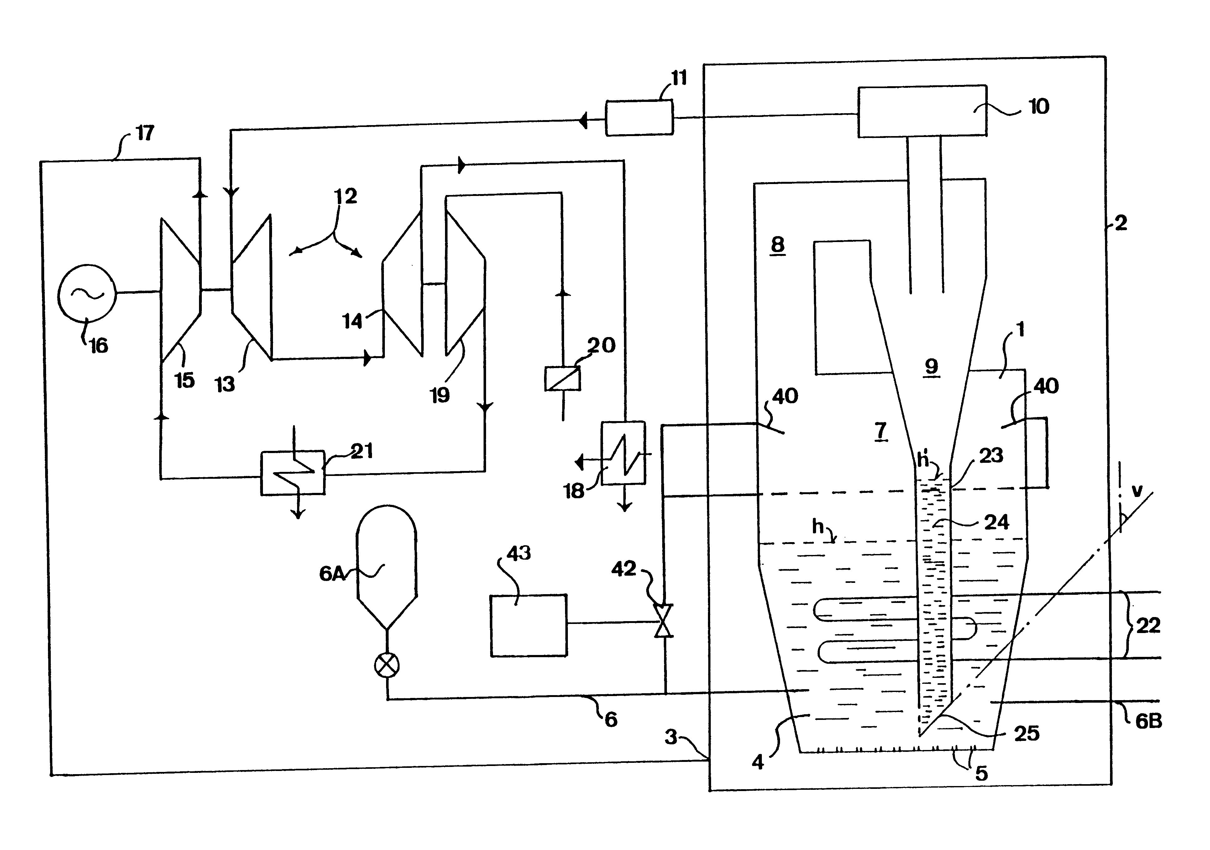
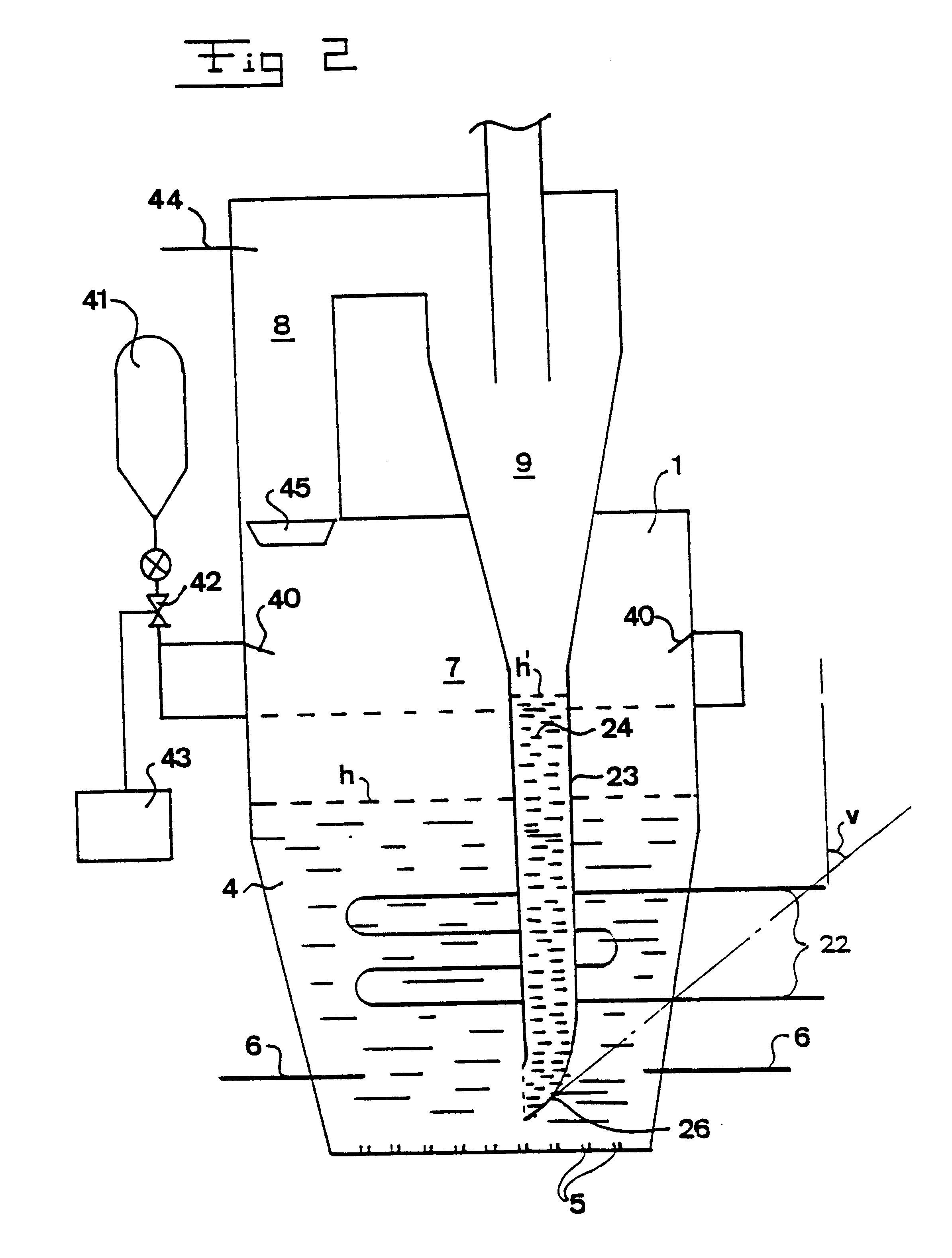
According to a further embodiment of the invention, the material separated is supplied to a channel in such a manner that a column of material is formed therein and the column of material, due to its weight, recirculates the material in a continuous flow through a passage having a constant opening area provided in the lower portion of the channel. Thus, the discharge of the material into the combustion chamber is performed merely by the weight of the column of material and without any influencing means from the outside such as previously used auxiliary means, e.g. ejectors or the like. The operation of the plant ensures that the column of material is filled from above by the separating member. Preferably, the height of the column of material exceeds the height of the bed. Furthermore, the gas from beneath is advantageously prevented from entering the channel.
Preferred embodiments of the combustion plant are described hereinafter. According to one embodiment, passive means are arranged in such a manner that a column of material is formed in the channel and that they form a passage having a constant flow area in the lower part of the channel, the passage permitting that the weight of the column of material discharges the material therethrough in the continuous flow. Thus, merely the weight of the column of material will provide a continuous and uniform recirculation of separated solid material to the combustion chamber. Since the recirculation device according to the invention comprises passive means not requiring any compressors or other drive members for overcoming the pressure difference and feed out the material from the column of material, this device will be very economically advantageous, particularly concerning the manufacturing as well as the operation of the plant. Furthermore, the erosion problems following the ejector feed of the material are avoided. Thus, since the recirculating channel according to the invention does not have any movable structural elements, it will have a very high reliability.

Problems solved by technology

However, such circulating beds operate with relatively high fluidizing velocities, in typical cases in the order of 5through 12 m / s.
This causes problems with erosion on, for instance, the steam tube arrangement provided in bed in such a way that the lifetime thereof significantly decreases.
Such a device leads to an intermittent recirculation of solid material.
However, such devices do not function in the way intended in the environment of a fluidized bed due to the movements occuring in the bed and the forces caused by these movements.
Furthermore, such devices are rapidly destroyed due to the aggressive, erosive and corrosive environment.
In order to provide a flow of material through the channel, such a device requires that gas is injected in the lower portion of the L-valve and, in order to provide stability, it is necessary to continuously measure the height of the column of material, which is very difficult, if not impossible, in the actual environment.
However, such an air injection is very expensive.
The gain of the absorbent utilization and the combustion efficiency is lost in the effect for the compressor providing primary air to the ejector.
In addition this method leads to erosion.
However, it is disadvantageous to need several different types of fuels for a single plant, since this makes the handling and the operation of the plant more complicated.
Such a combustion of carbon is disadvantageous since the combustion gases from the complementary combustion will not pass the bed, in which there is a sulphur absorbent, prior to leaving the plant.
Another problem of this method is that it may be difficult to combust a fuel, such as carbon, in the freeboard during part load since the temperature in the freeboard then may be too low.
Without any recirculation, it has been recognized that a certain part, an unacceptable part, of carbon supplied has passed the dust purification equipment and the turbine in an unburnt state.
This problem gives great losses and frequently causes fire in the this equipment.
Due to the relatively great content of undesirable substances, such as sulphur, in particulate fuels, this has previously not been practically usable for such freeboard combustion.

Method used


Image

  • Method and apparatus for burning fuel in the free board of a pressurized fluidized bed with solids recirculation
  • Method and apparatus for burning fuel in the free board of a pressurized fluidized bed with solids recirculation
  • Method and apparatus for burning fuel in the free board of a pressurized fluidized bed with solids recirculation

Examples


Embodiment Construction

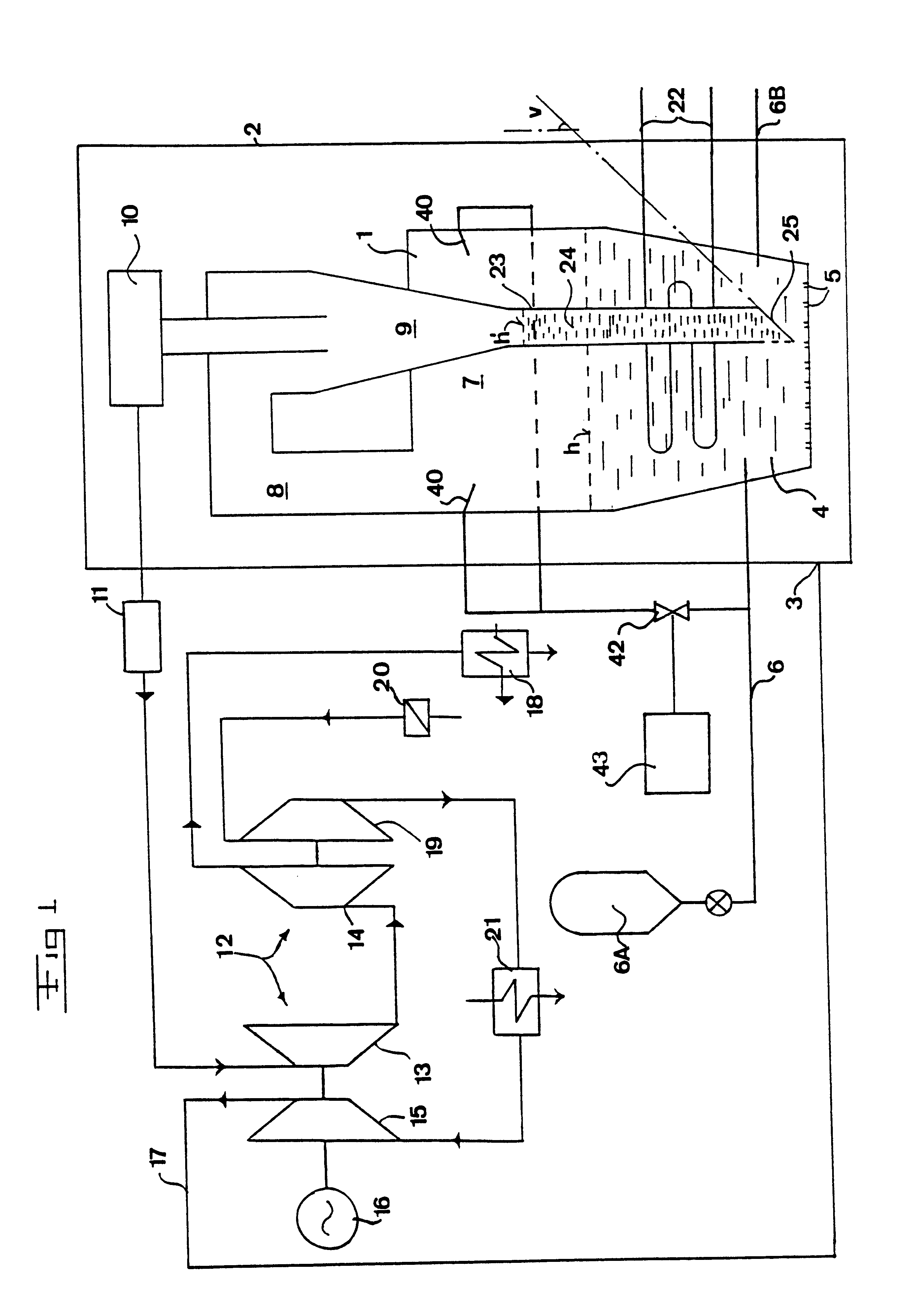
The invention will now be explained with a reference to a so-called PFBC-power plant (pressurized, fluidized bed combustion). However, it should be noted that the invention also is applicable to other types of plants, in particular combustion plants without power production. A PFBC-power plant, i.e. a plant for the combustion of particulate fuel in a pressurized, fluidized bed, is schematically disclosed in FIG. 1. The plant comprises a combustion chamber 1 being housed in a pressure vessel 2, having a volume in the order of 10.sup.4 m.sup.3 and which may be pressurized to, for example, between 7 and 30 bars (abs). Compressed oxygen-containing gas, in the example disclosed here, is supplied to the pressure vessel 2 at 3 for pressurizing the combustion chamber 1 and for fluidizing a bed 4 in the combustion chamber 1. The compressed air is supplied to the combustion chamber 1 via schematically indicated fluidizing nozzles 5 being provided in the bottom of the combustion chamber 1 for ...


PUM


Abstract

A method of combustion in a pressurized, fluidized bed and in the freeboard thereof. The combustion method is further characterized by the recirculation of solid sulfur absorbing materials. A gas channel, designed so as to prevent fluidizing gas from entering the channel from below, is provided such that it opens to the freeboard and to a separating member which separates particulate matter from the combustion gasses.

Description

BACKGROUND OF THE INVENTION AND PRIOR ARTThe present invention refers to a method of combustion in a combustion chamber enclosing a pressurized fluidized bed and a space located above the bed, comprising the steps of: feeding an oxygen-containing gas into the bed; supplying a fuel to the bed; supplying a particulate absorbent to the bed for the absorption of undesirable substances released during the combustion; collecting in the space combustion gases formed during the combustion; discharging the combustion gases from the combustion chamber; and separating solid material from the combustion gases. Moreover, the invention refers to a combustion plant comprising a combustion chamber, which is provided to enclose a pressurized fluidized bed and a space located above the bed and in which a combustion of a fuel is intended to be performed while forming combustion gases, at least a first fuel supply member arranged to supply the fuel to the bed, means arranged to supply an oxygen-contain...

Claims


Application Information

Patent Timeline
IPC IPC(8): F01K23/06F23C6/04F23C10/00F23C10/16F23C6/00F23C10/10F23J7/00F23C10/22
CPCF01K23/062F23C6/047F23J7/00F23C10/16F23C10/10
Inventor ADAMS, CHRISTOPHERANDERSON, JIMANDERSSON, MATSBRANNSTROM, ROINEWEATHERBY, JOHN
Owner GENERAL ELECTRIC TECH GMBH
Learn More