Combined steam and gas turbine engine with magnetic transmission

a gas turbine engine and magnetic transmission technology, which is applied in the direction of machines/engines, lighting and heating apparatus, etc., can solve the problems of limited specific power, limited operating pressure ratio, and limited thermal energy generation from fuel

Inactive Publication Date: 2001-07-24
TANIGAWA HIROYASU +1
View PDF15 Cites 463 Cited by
  • Summary
  • Abstract
  • Description
  • Claims
  • Application Information

AI Technical Summary

Problems solved by technology

The operating pressure ratio and the specific power are limited by the heat durability of the turbine system.
A burden for increasing the operatin

Method used


Image

  • Combined steam and gas turbine engine with magnetic transmission
  • Combined steam and gas turbine engine with magnetic transmission
  • Combined steam and gas turbine engine with magnetic transmission

Examples


first embodiment

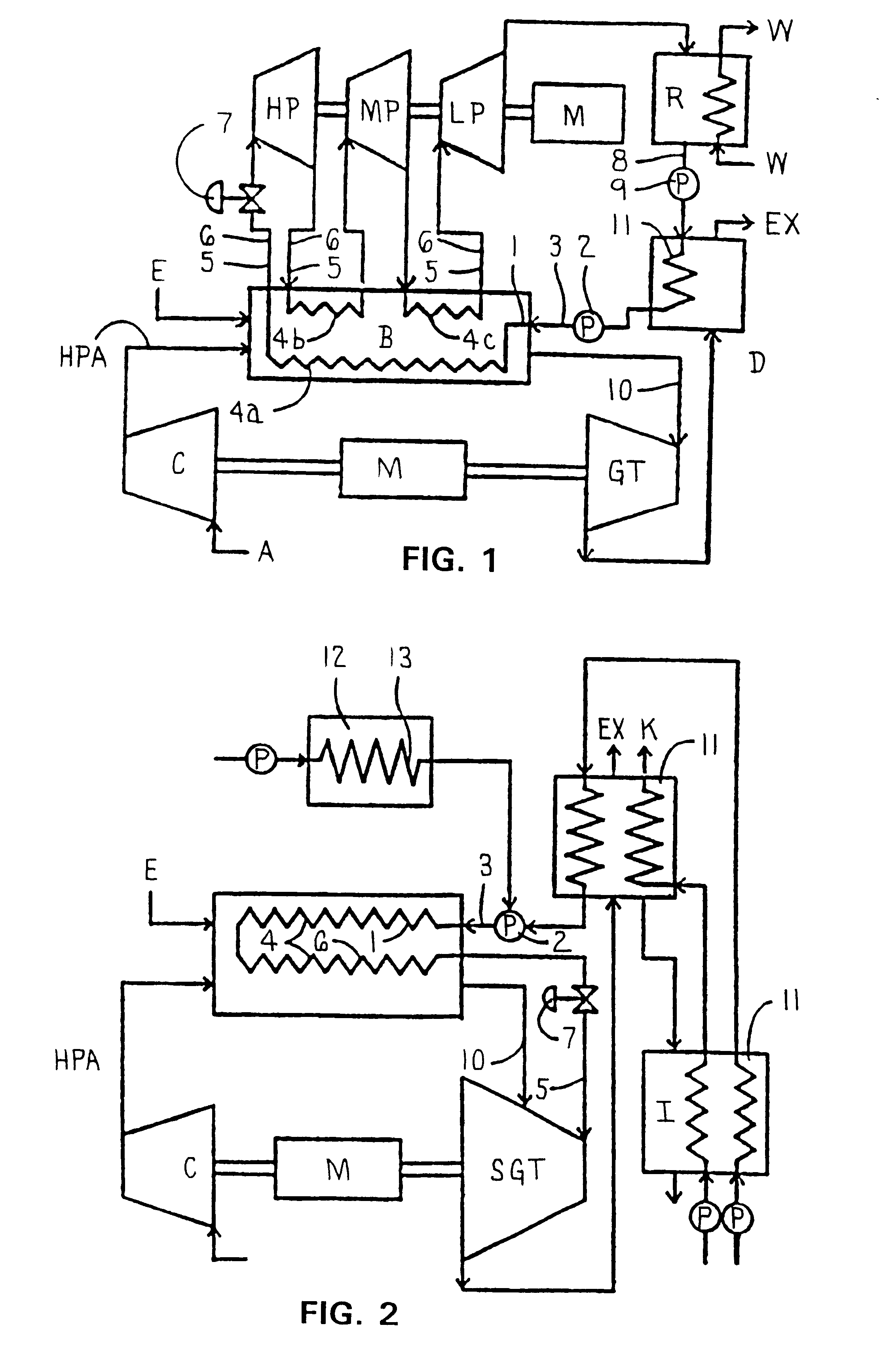
FIG. 1 shows a schematic diagram of the invention for explaining a principle of this invention.

In FIG. 1, the system comprises a compressor, a long dimension combustion chamber in which high pressure combustion takes place, a gas turbine, steam turbines, and a power generator.

The thermal efficiency of the gas turbine is dependent on the operating temperature, however, there exists a limit to the operating temperature due to the system being destroyed due to the materials of the system failing.

To operate the system at its maximum thermal efficiency, the specific pressure must be raised, the velocity of the combustion gas must be at a high speed, and the combustion gas mass flow becomes larger, so the system is arranged as follows.

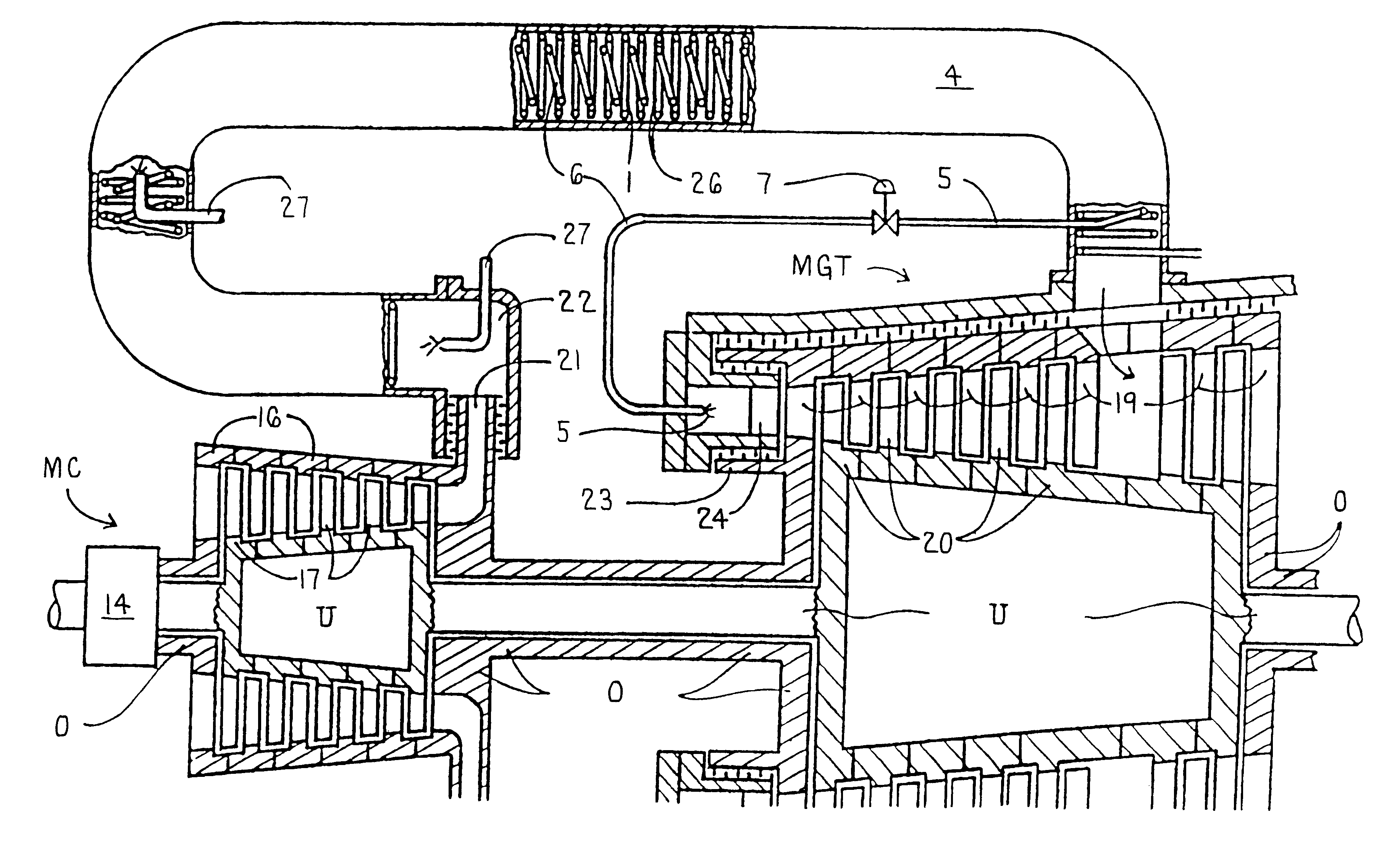
A water pipe 1 is helically welded around a combustion chamber B and the combustion chamber becomes a heat exchanger 4a that has a long dimension and high pressure combustion condition. Internal steam pipes 6,6 are also arranged helically in which the pressu...
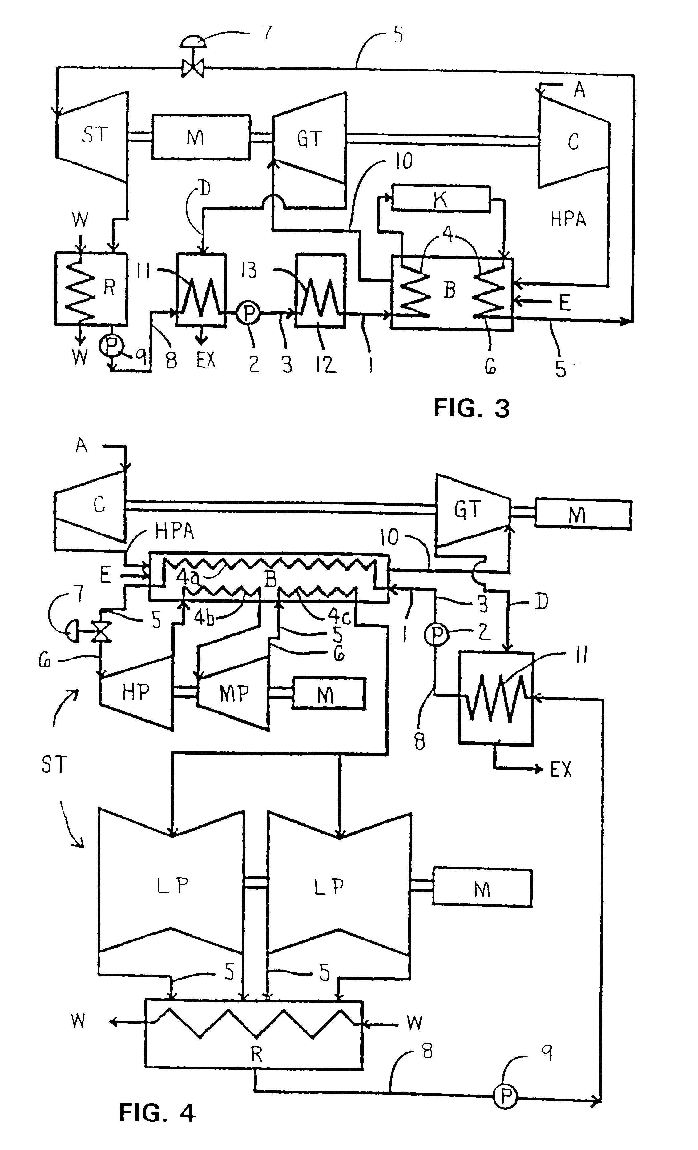
third embodiment

FIG. 3 shows this invention in which a mono-axle combined steam and gas turbine engine will be explained.

second embodiment

The difference between the second embodiment is that the steam turbine and the gas turbine are arranged independently and a waste combustion furnace 13 is disposed after the heat recovery heat exchanger 11.

Since the system is provided with a combustion chamber-heat exchanger 4, the combustion gas mass flow of the system is increased by four times as much as the conventional gas turbine system and the specific power of the gas turbine engine is increased. Further, the operation pressure ratio of the gas turbine engine is increased, but does not exceed the durability temperature of the system, and the thermal efficiency of the gas turbine cycle and the steam turbine cycle is considerably increased.

Since the specific power and the thermal efficiency are dependent on the operation pressure ratio, and the operation pressure ratio is increased by the use of the combustion chamber-heat exchanger 4, the thermal efficiency of both the gas turbine engine and the steam turbine engine increase....


PUM


Abstract

In a combined steam and gas turbine engine cycle, a combustion chamber is made durable against high pressure and enlarged in length to increase the operation pressure ratio, without exceeding the heat durability temperature of the system while increasing the fuel combustion gas mass flow four times as much as the conventional turbine system and simultaneously for greatly raising the thermal efficiency of the system and specific power of the combined steam and gas turbine engine.Water pipes and steam pipes are arranged inside the combustion chamber so that the combustion chamber can function as a heat exchanger and thereby convert most of the combustion thermal energy into super-critical steam energy for driving a steam turbine and subsequently raising the operation pressure ratio and the thermal efficiencies of the steam turbine cycle and gas turbine cycle. The combustion gas mass flow can be also increased by four times as much as the conventional turbine system (up to the theoretical air to fuel ratio) and the thermal efficiency and the specific power of the gas turbine cycle are considerably increased.Further, the thermal efficiency of the combined system is improved by installing a magnetic friction power transmission system to transmit the power of the system to outer loads.

Description

This application is the national stage of International Application PCT / JP97 / 02250 filed Jun. 27, 1997.The invention relates to a combined steam and gas turbine engine. More particularly, to a gas turbine engine combustion chamber having a helical welded structure heat exchanger on an outside surface thereof for cooling the combustion chamber with water and thereby raise the combustion gas pressure higher than a conventional turbine combustion chamber and further enlarge the dimensions of the combustion chamber for increasing the fuel supply means three times as much. Further, the invention relates to a combined steam and gas turbine engine in which inside of the combustion chamber, a steam heater is disposed and the combustion gas drives a gas turbine and the steam drives a steam turbine. The invention also relates to a combined steam and gas turbine system having a magnetic friction power transmission system which allows an internal axis and an outside axis to rotate in an opposit...

Claims


Application Information

Patent Timeline
IPC IPC(8): F01D15/00F01K23/06F02C3/00F01K21/04F01K21/00F01D15/12F16H49/00F02C3/067F02C7/36F02C7/00F23R3/00
CPCF01D15/12F01K21/047F01K23/06F02C3/067F16H49/005F23R3/005F02C7/36Y02E20/16Y02T50/675Y10S74/04Y02T50/60
Inventor TANIGAWA, HIROYASUTANIGAWA, KAZUNAGA
Owner TANIGAWA HIROYASU
Why Eureka
Try Eureka