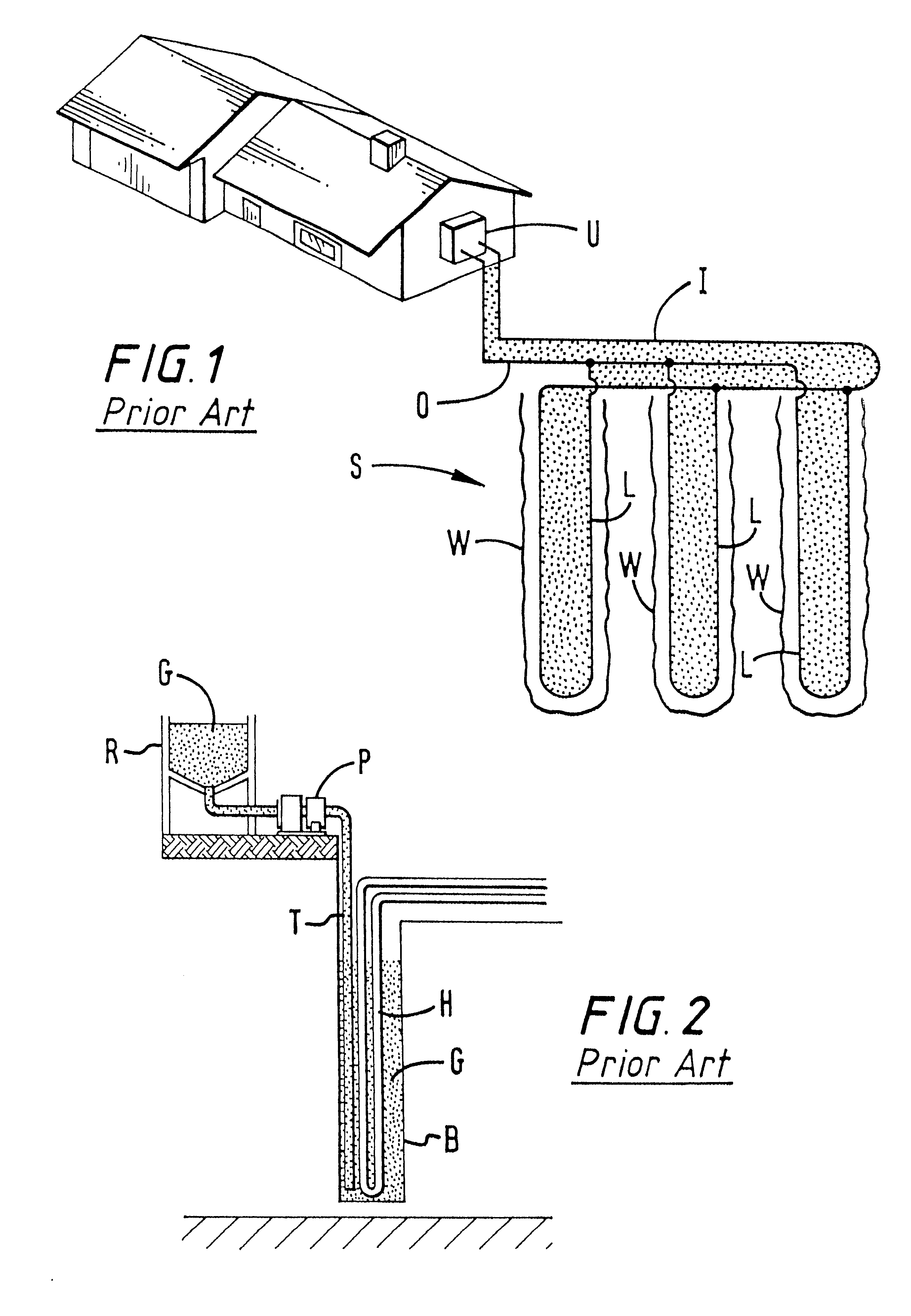
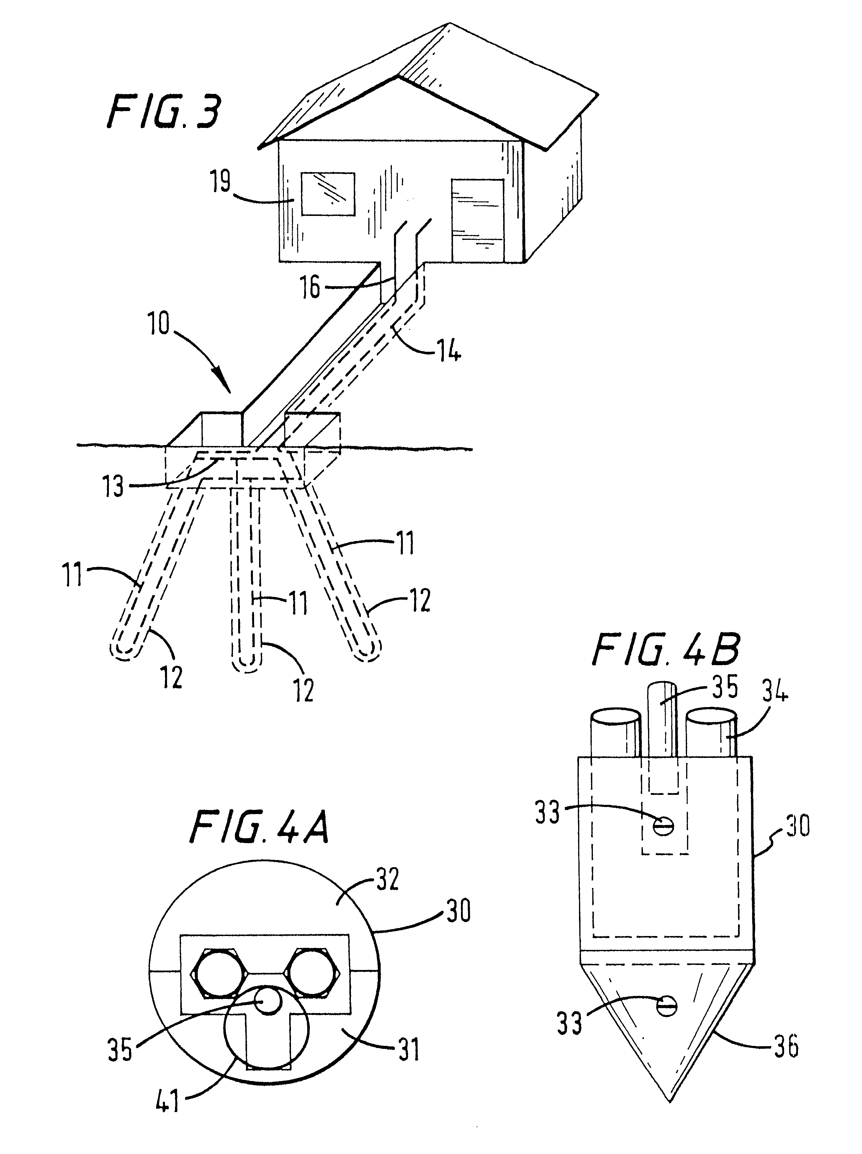
One reason ground source heat pumps have not been more widely used in the past is because of the expense involved in the design and installation of the circulating
fluid pipe loop which must be buried in the ground.
The uncertainty of the installation costs coupled with the uncertainty of the resulting operating efficiencies have made it difficult for a customer to predict the operating costs and the financial payback associated with installing a ground source
heat pump system.
The cost for the installation of certain prior art vertical ground source heat loops can account for nearly half of the total cost incurred in the installation of a
geothermal heat pump system.
Several problems can arise in such methods: loop "
insertion" difficulties caused by loop
buoyancy;
thermal conductivity and installation difficulties of borehole backfill materials; and environmental concerns.
Although the drilling of the hole may be relatively easy, certain problems may be encountered in inserting the loop.
This pipe material also has relatively poor stiffness.
Since the pipe has poor longitudinal stiffness, the pipe tends to bend or curl inside the well, creating additional frictional drag against the well wall until the pipe can be pushed no deeper.
Even when the pipe is filled with water, the loop still maintains considerable
buoyancy because the drilled hole is filled with dense drilling mud.
The considerable efforts made to overcome buoyancy of the loop caused by the density of the
drill fluid are
time consuming, expensive, and hazardous to the integrity of the loop.
Great expense and many tests and studies have been performed in a search for an optimum thermally conductive material that can be economically placed in the annular space between the loop pipe and the
wellbore wall.
This insulating airspace results in "hot loops", and the
heat pump system either works poorly or not at all.
Although these grouts seem to work well in testing, there is great resistance from the field installers.
The mixture can be expensive to
handle, difficult to mix, even more difficult to pump, and extremely rough on equipment because of the abrasion.
In addition, placing of the material in the borehole is difficult to control and monitor.
If grouting is attempted from the surface, "bridging" can occur resulting in a partially filled hole.
If grouting from the bottom of the hole, "channeling" can occur, again resulting in a partially grouted hole.
When the water subsides in the borehole, this leaves air spaces, thus insulating the loop and reducing the efficiency of the system.
An additional
disadvantage is that the voids from channeling as well as the interstitial spacing between the individual sand (or other
solid particles) create permeability.
Permeability that creates a vertical communication path by which the ground water system could be contaminated by surface spills is an environmental concern.
The prior art cementitious grouts, developed to overcome the permeability objection, have some unique problems of their own.
In addition to all of the handling, mixing, pumping, abrasion, and
conductivity problems of the High Solids Thermally Conductive Grouts, the "heat of hydration" generated when
cement cures, causes
grout to "shrink" away from the
polyethylene pipe.
Although the permeability of the cured
grout itself is very low, a flow path may now exist between the
polyethylene pipe and the
grout--again insulating the loop and threatening the environment.
Because of its inherent structure,
polyethylene is a very high molecular weight
wax or paraffin, and does not bond well with anything, even under laboratory controlled conditions.
Attempts to control grout shrinkage and
cement to polyethylene bonding in the field were proven unsuccessful.
The trenching and manifolding of the surface pipe typically takes as much time as the
wellbore drilling and pipe installation.

