Waste processing system and fuel reformer used in the waste processing system

a waste processing system and fuel reformer technology, applied in the direction of machines/engines, combustion types, lighting and heating apparatuses, etc., can solve the problems of high temperature gas of raw fuel, large apparatus size, and difficult to remove dioxin, so as to suppress nox generation, stably decompose generated dioxin, and decompose generated dioxin

Inactive Publication Date: 2001-09-04
HITACHI LTD
View PDF12 Cites 9 Cited by
  • Summary
  • Abstract
  • Description
  • Claims
  • Application Information

AI Technical Summary

Benefits of technology

The first objective of the present invention is to provide a waste-to-energy incineration system which are able to stably decompose generated dioxin, in which the composition and the heat value of exhaust gas largely changes in a long and a short periods, and a fuel reformer used there.
The second objective of the present invention is to provide a waste-

Problems solved by technology

On the other hand, in an direct heat exchange type fuel reformer, the heat required for reforming raw fuel is directly given to raw fuel flowing in a fuel flowing path by partial oxidization, which results in a high temperature gas of raw fuel.
Since the previously-mentioned indirect heat exchange type fuel reformer include a burner for heating a reaction tube, such a fuel reformer has a problem in that the size of the apparatus becomes large, and an external heat source has to be provided.
Especially, removal of dioxin has been a very pr

Method used


Image

  • Waste processing system and fuel reformer used in the waste processing system
  • Waste processing system and fuel reformer used in the waste processing system
  • Waste processing system and fuel reformer used in the waste processing system

Examples


Embodiment Construction

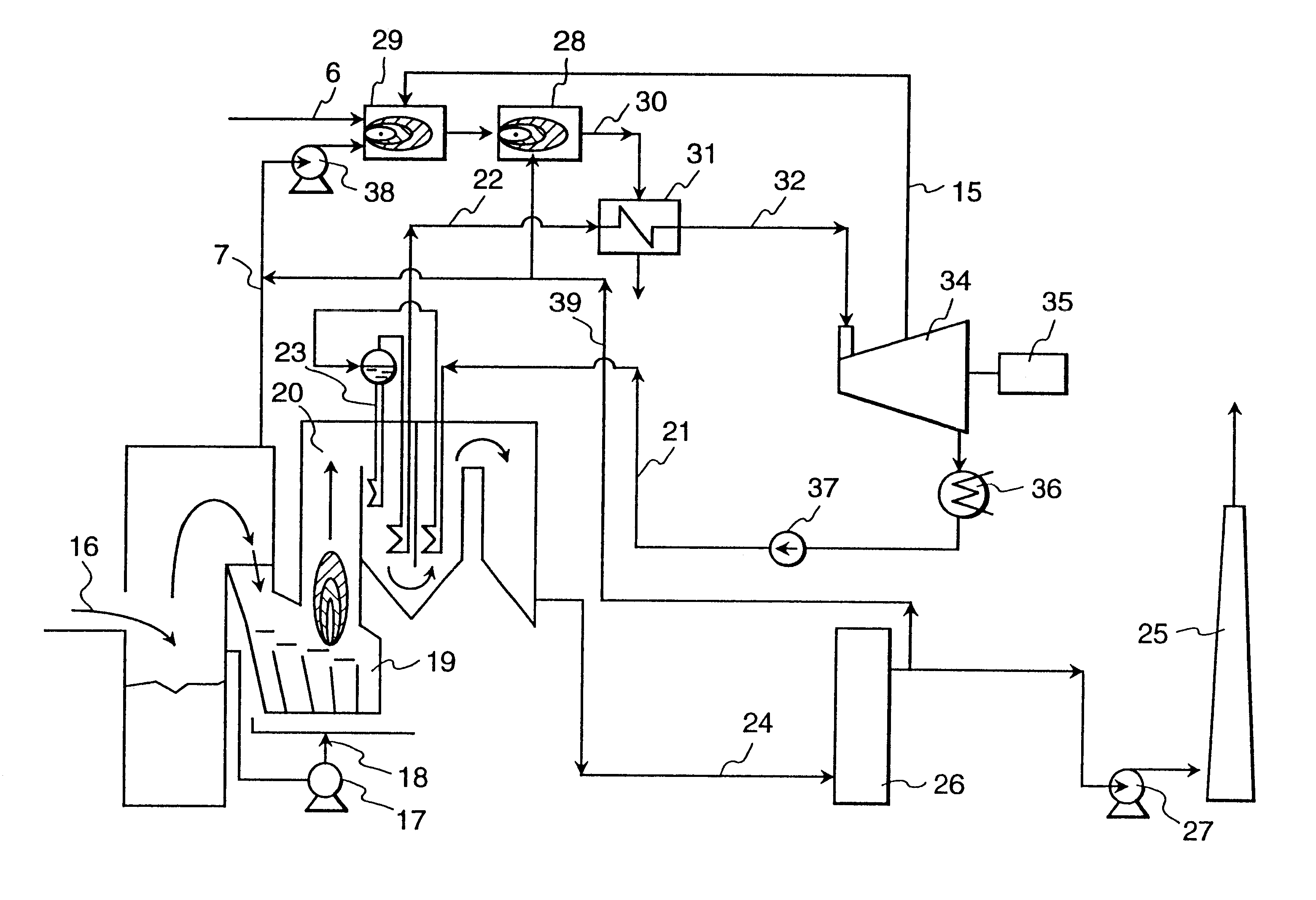
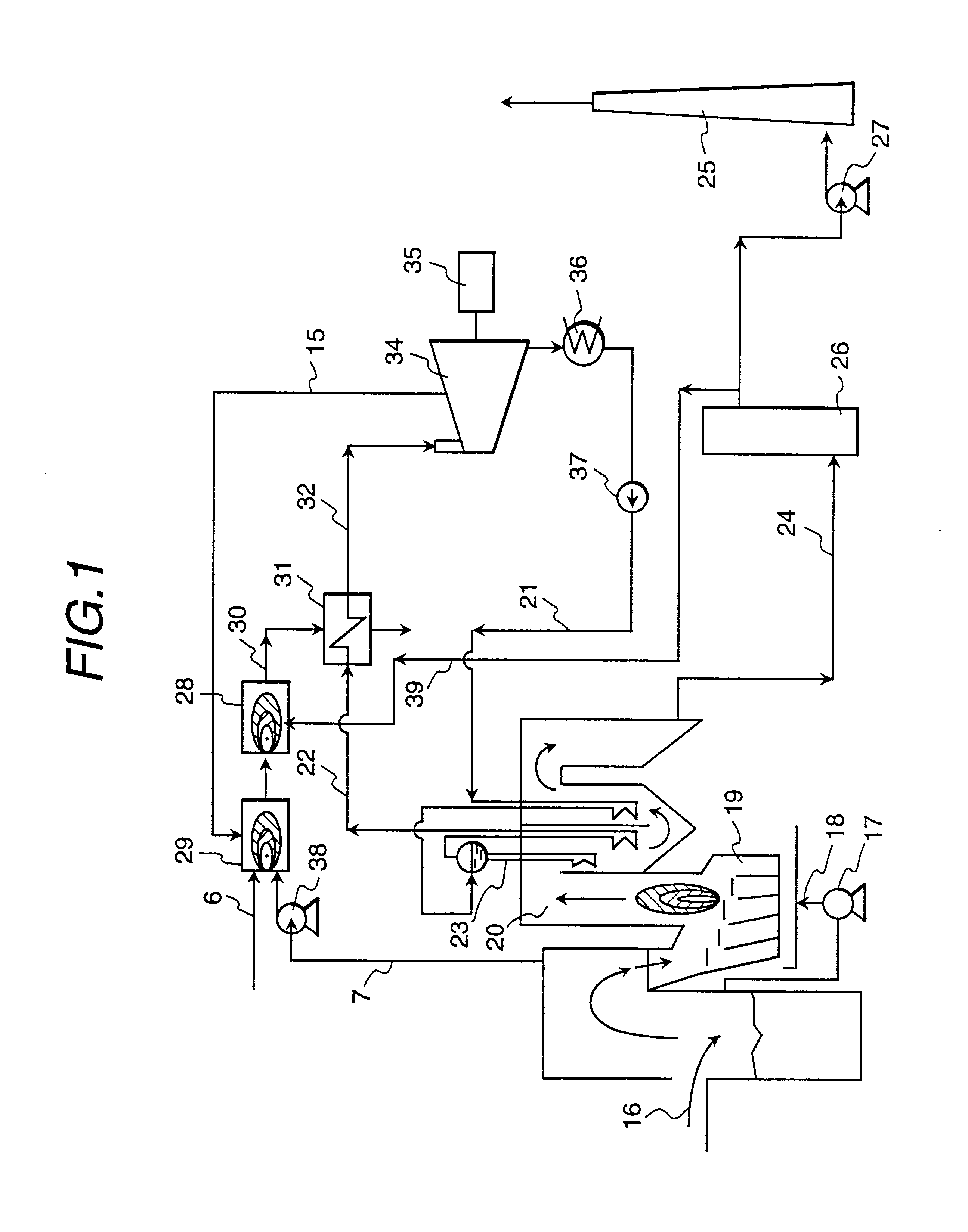
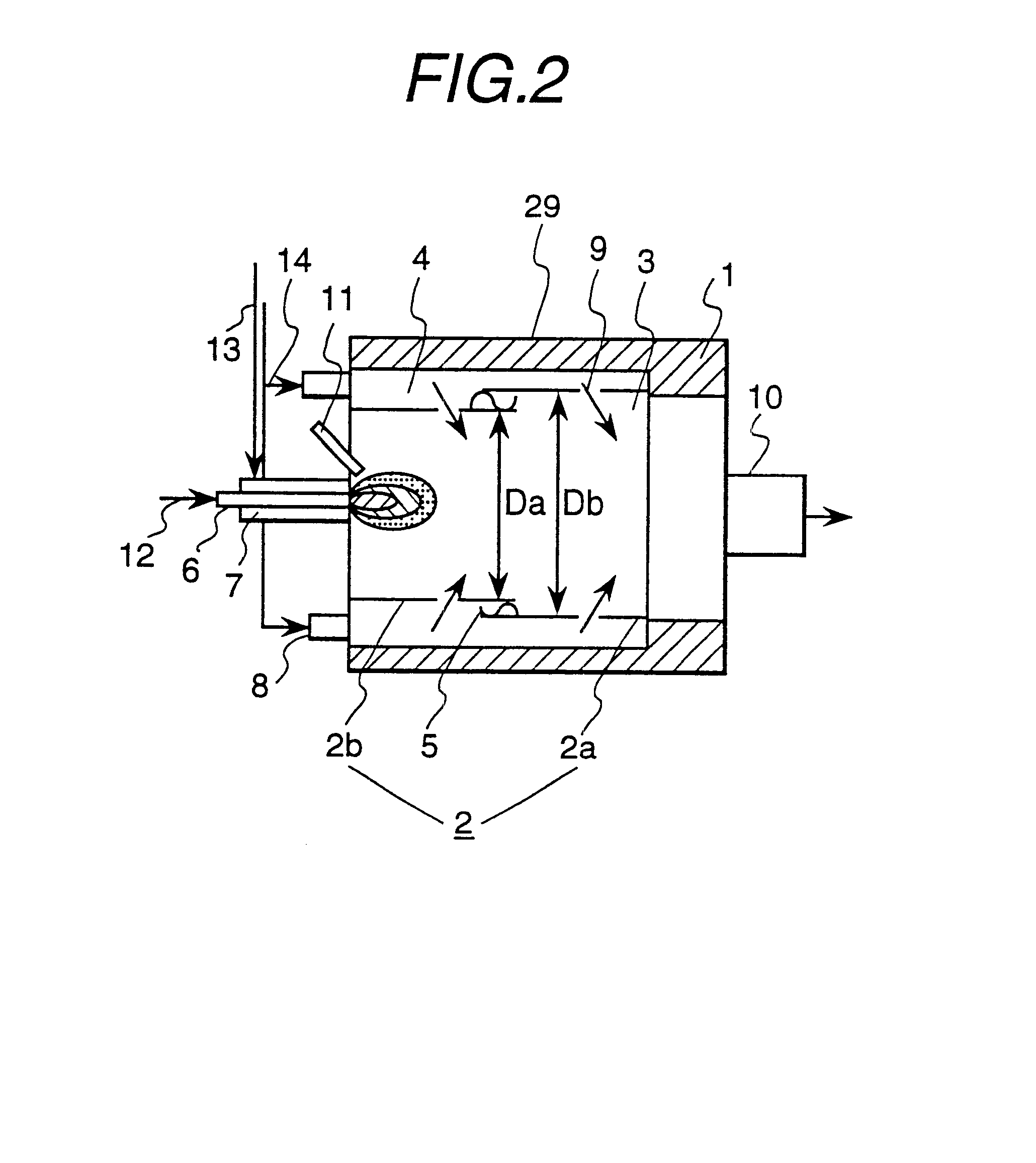
At first, details of the present invention will be explained with reference to an embodiment shown in FIG. 1-FIG. 4. FIG. 1 is a system diagram of a waste-to-energy incineration system of an embodiment according to the present invention, and FIG. 2 is a vertical sectional view of a fuel reformer of an embodiment. In each of FIG. 3-FIG. 5, a composition of variation examples of the waste-to-energy incineration system shown in FIG. 1, are shown.

As shown in FIG. 1, the waste-to-energy incineration system is divided into main two systems, that is, a steam turbine systems and an exhaust gas system including a fuel reformer. In an incinerator 19, a part for storing waste 16 is provided, and air is injected into the incinerator 19 from the part for storing waste 16 by a compressed fan 17. The air injected into the incinerator 19 is used as waste burning air. The burned waste gas 20 generated in the incinerator is sent to a dust collector 26 via an exhaust gas pipe 24 after flowing through ...


PUM

PropertyMeasurementUnit
Energyaaaaaaaaaa

Abstract

A waste-to-energy incineration system, in which the amount and heat value of exhaust gas largely changes in long and short periods, comprises an incinerator for burning waste, a boiler in the incinerator for generating steam with exhaust heat generated by the incinerator, a superheater for superheating steam generated in the boiler, a steam turbine driven by steam superheated by the superheater, a generator driven by the steam turbine, a fuel reformer for reforming source fuel, and a combustor burning fuel gas reformed by the fuel reformer and at least a part of exhaust gas led from the incinerator which is able to stably decompose generated dioxin in waste incineration exhaust gas.

Description

1. Field of the InventionThe present invention relates to a fuel reformer and a waste processing system including reformer, especially to a direct heat exchange type, catalystless fuel reformer, and a waste-to-energy incineration system in which a direct heat exchange type, catalystless fuel reformer is adopted.2. Description of Related ArtAs a fuel reformer for reforming source fuel such as hydrocarbon material to gas containing hydrogen, an indirect heat exchange type fuel reformer or a direct heat exchange type reformer has been largely used. Further, there are two types of fuel reformer, that is, a fuel reformer using catalyst and a fuel reformer without using catalyst.In an indirect heat exchange type fuel reformer, a reaction tube and a burner are provided. While the reaction tube is heated by the combustion gas from the burner, raw gas enters the reaction tune at an end of the reaction tube. Further, the raw gas is partially oxidized (so-called partial combustion), and reform...

Claims


Application Information

Patent Timeline
IPC IPC(8): B01B1/00C01B3/38C01B3/00F01K3/00F01K3/24F23G5/027F23J15/08F23G5/46
CPCB01B1/005C01B3/38F01K3/247F23G5/46F23J15/08F23G5/0276F02G2254/11Y02E20/12F23G2202/106F23G2206/10
Inventor OKUSAWA, TSUTOMUKOYAMA, KAZUHITOYAMAGISHI, MASAHIKOHATAMIYA, SHIGEOAJIRO, TAIKOSUNOU, MEGUMIISHIGAKI, YUKIOTOKUNAGA, KENJI
Owner HITACHI LTD
Why Eureka
Try Eureka