Method of reducing RIE lag for deep trench silicon etching

a deep trench silicon and etching technology, applied in the direction of transistors, basic electric elements, electric devices, etc., can solve the problems of significant blockage, difficult to control the passivation of the dt side wall (sw) passageway, and the rie process is relatively complex, so as to reduce or at least minimize the rie lag

Inactive Publication Date: 2001-09-04
INFINEON TECH AG +1
View PDF4 Cites 82 Cited by
  • Summary
  • Abstract
  • Description
  • Claims
  • Application Information

AI Technical Summary

Benefits of technology

Accordingly, it is a primary object of the invention to provide a method of eliminating or at least minimizing RIE lag

Problems solved by technology

The DT Si RIE process is relatively complex.
With the requirement of GR shrinkage, the control of DT side wall (SW) passivation has become a fundamental issue and an impediment in achieving deeper DTs.
This blockage is significant for smaller GR etch process in standard semiconductor manufacturing processes.
Etching deep or high aspect ratio trench hole

Method used


Image

  • Method of reducing RIE lag for deep trench silicon etching
  • Method of reducing RIE lag for deep trench silicon etching
  • Method of reducing RIE lag for deep trench silicon etching

Examples


Embodiment Construction

.

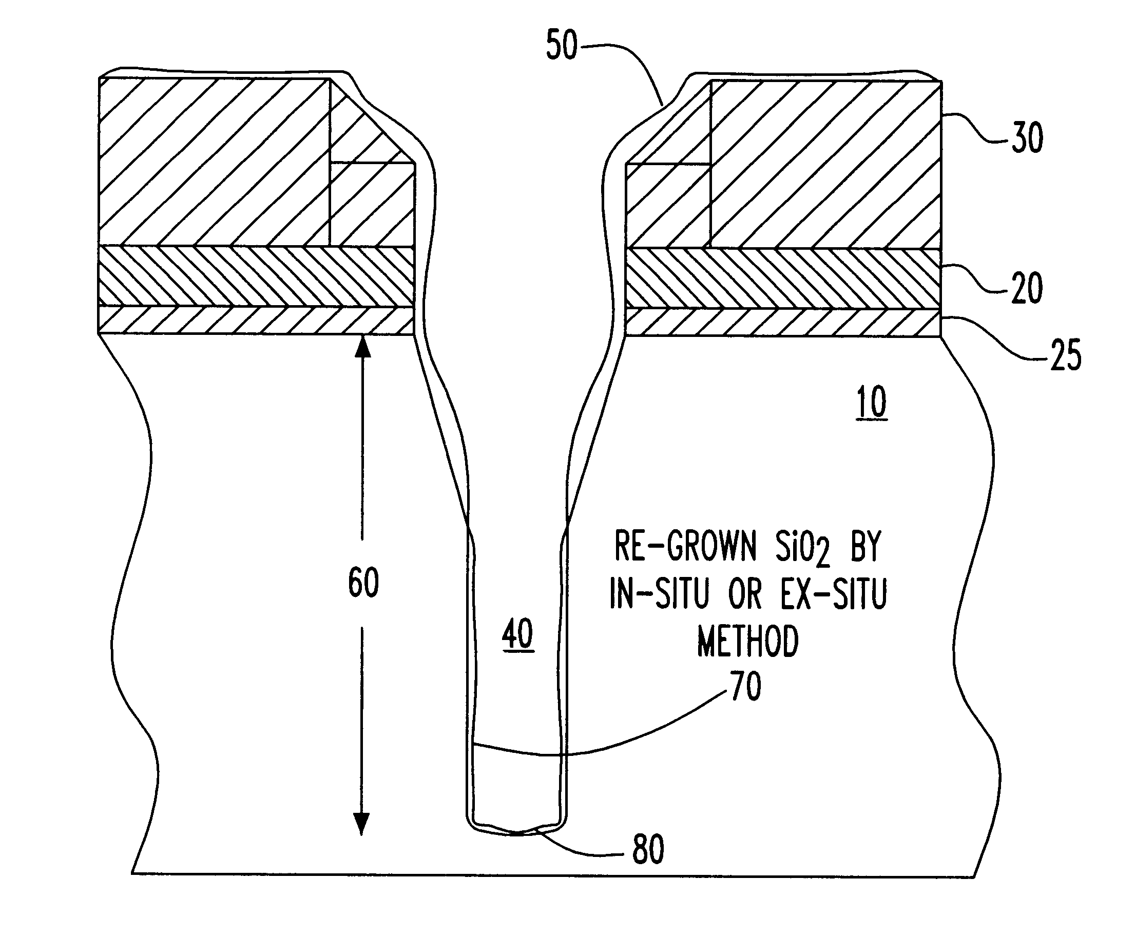
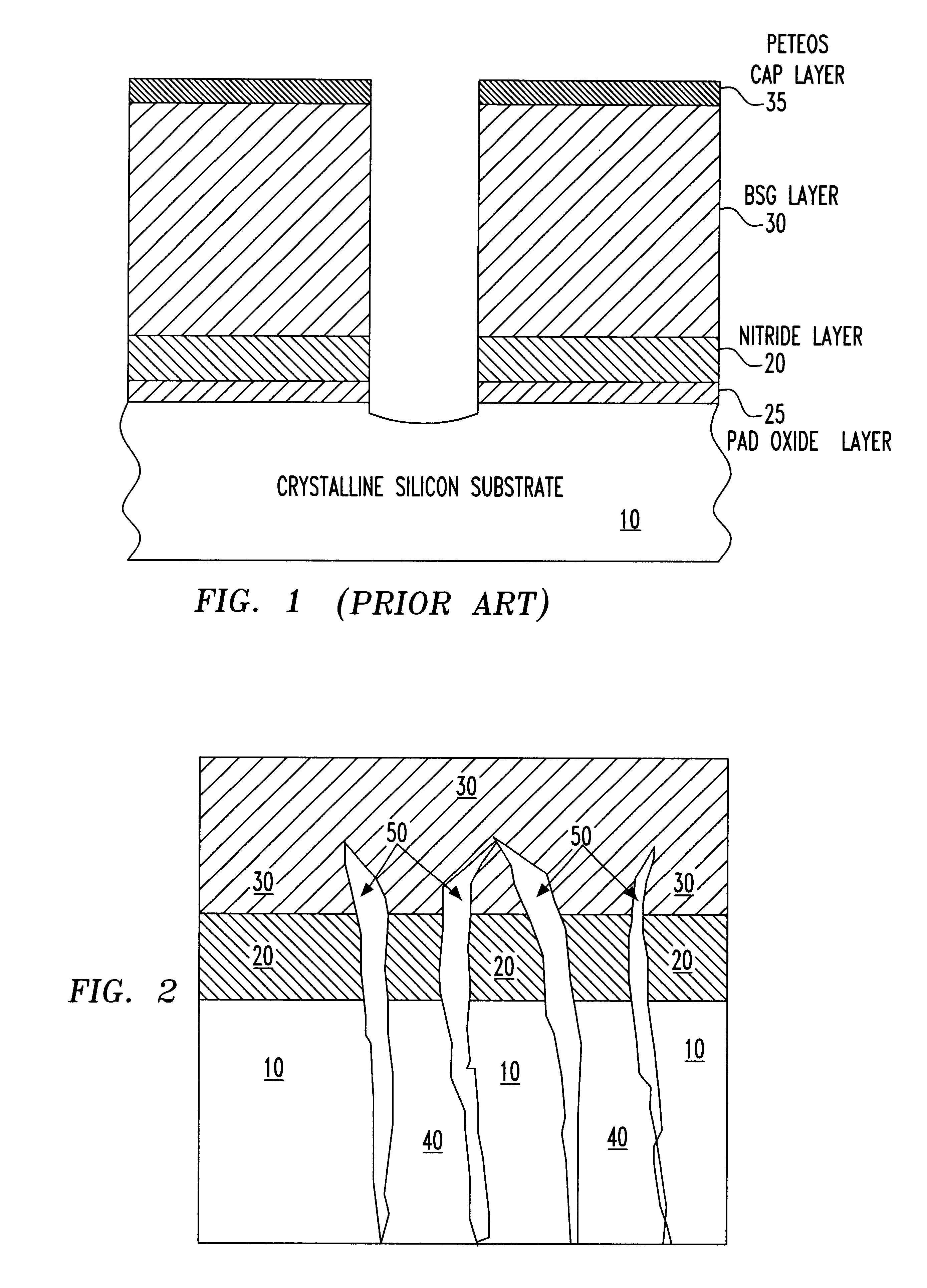
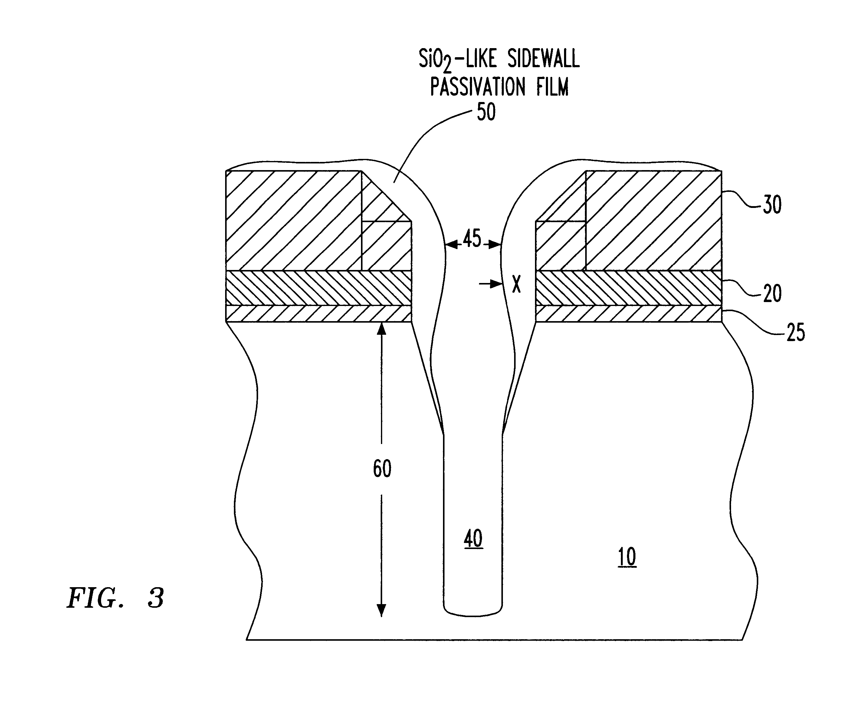
Referring back to the primary object of the invention referring to the RIE lag defined as neutral and ion fluxes at the trench bottom due to the constriction of the trench opening by side wall film deposition, it is known that since the thickness of the side wall film is time dependant, thereby affecting the trench depth, etching deeper trenches aggravates this problem. Since most of the trenches so far have been of smaller aspect ratio (<5:1), the proposed solution has not been so far disclosed. The main contributors limiting DT depth are, therefore, the ion-neutral fluxes and the time dependent formation of side wall passivation.

The uncovering of this second contributor has led to inventing a solution that minimizes or eliminates the RIE lag problem, originating from this second factor. The process flow of the invention is shown below with each process step shown schematically in FIGS. 1-6 and is discussed in detail in the following steps 1-5.

In the preferred embodiment, the foll...


PUM


Abstract

A method of minimizing RIE lag (i.e., the neutral and ion fluxes at the bottom of a deep trench (DT) created during the construction of the trench opening using a side wall film deposition)) in DRAMs having a large aspect ratio (i.e., <30:1) is described. The method forms a passivation film to the extent necessary for preventing isotropic etching of the substrate, hence maintaining the required profile and the shape of the DT within the substrate. The RIE process described provides a partial DT etched into a substrate to achieve the predetermined depth. The passivation film is allowed to grow to a certain thickness still below the extent that it would close the opening of the deep trench. Alternatively, the passivation film is removed by a non-RIE etching process. The non-RIE process that removes the film can be wet etched with chemicals, such as hydrofluoric acid (buffered or non buffered) or, alternatively, using vapor phase and/or non-ionized chemicals, such as anhydrous hydrofluoric acid. The controlled thickness of the film allows achieving a predetermined DT depth for high aspect ratio structures.

Description

The present invention is related to the fabrication of semiconductor devices, and more particularly, to etching a high aspect ratio deep trench DRAM to build capacitors in Si substrates.The fabrication of deep trenches (DT) in Si substrates is one method of making charge storage cells, referred to as DT capacitors. A deep hole of somewhat conical shape is etched out of a Si substrate wafer by a commonly used dry etch method known as reactive ion etching (RIE). A dielectric material usually with a high dielectric constant is deposited in a form of a conformal layer inside a DT. The inner surface on one side of the trench, and a conductive or a semiconductor material fill on the other side of the dielectric material serve as capacitor plates. The film thickness of the dielectric material is inversely proportional to the charge the film can hold. Thus, the thickness of the film is kept to a minimum to the extent allowed by the process capability. The surface area of the dielectric film...

Claims


Application Information

Patent Timeline
IPC IPC(8): H01L21/02H01L21/308H01L21/3065H01L21/302H01L21/8242H01L27/108
CPCH01L21/3081H01L21/3065
Inventor NAEEM, MUNIR D.MATHAD, GANGADHARA S.KIM, BYEONG YEOLKUDELKA, STEPHAN P.LEE, BRIAN S.LEE, HEONMORALES, ELIZABETHPARK, YOUNG-JINRANADE, RAJIV M.
Owner INFINEON TECH AG
Why Eureka
Try Eureka