
Apparatus and method forming thin film

a thin film and apparatus technology, applied in the direction of superimposed coating process, instruments, optical elements, etc., can solve the problems of requiring several hours of condensation curing step, disadvantageous equipment for producing coating films, industrial-scale production of films with a higher refractive index, etc., to achieve long-term stability, reproducibility, and stable operation

Inactive Publication Date: 2001-09-11
SHINCRON KK
View PDF15 Cites 52 Cited by
  • Summary
  • Abstract
  • Description
  • Claims
  • Application Information

AI Technical Summary

Benefits of technology

is to provide an apparatus for forming a thin film having an medium refractive index at low temperature and ensuring long-term, stable operation and reproducibility.

Problems solved by technology

Therefore, a facility for producing the coating film must disadvantageously be equipped with a plurality of dipping apparatus.
In addition, a conventional method for forming a hard coating film requires a condensation-curing step requiring several hours.
However, satisfactory, industrial-scale production of a film having a higher refractive index with a constant refractive index at the top surface of a thin film through plasma CVD or by use of a refractive index-graded film which matches any substrate has not been attained thus far, due to restriction of a production apparatus and fabrication of a production apparatus.
Specifically, when direct plasma CVD is employed, stable operation of a CVD apparatus while constant component proportions of gasified materials are maintained is difficult, due to difficulty in flow control of a monomer serving as a TiO.sub.2 source among two categories of gasified substances.

Method used


Image

  • Apparatus and method forming thin film
  • Apparatus and method forming thin film
  • Apparatus and method forming thin film

Examples


Embodiment Construction

The present invention will next be described with reference to the drawings. The below-described parts and locations should not be construed as limiting the invention thereto, and a multitude of variations are encompassed by the scope of the invention.

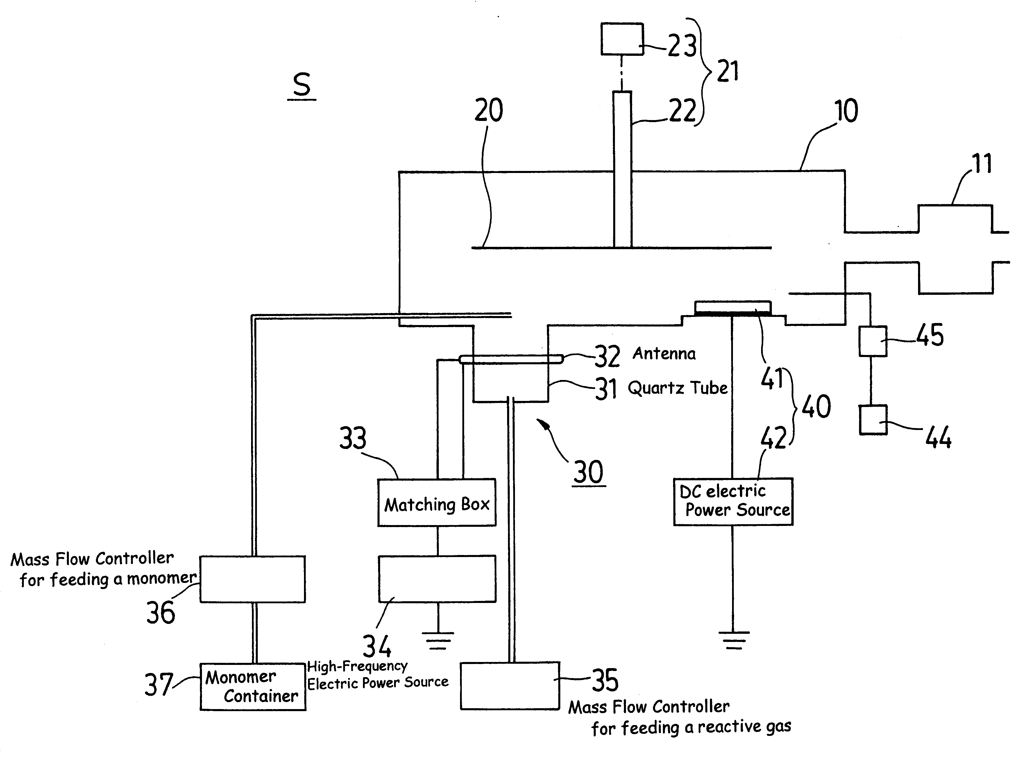
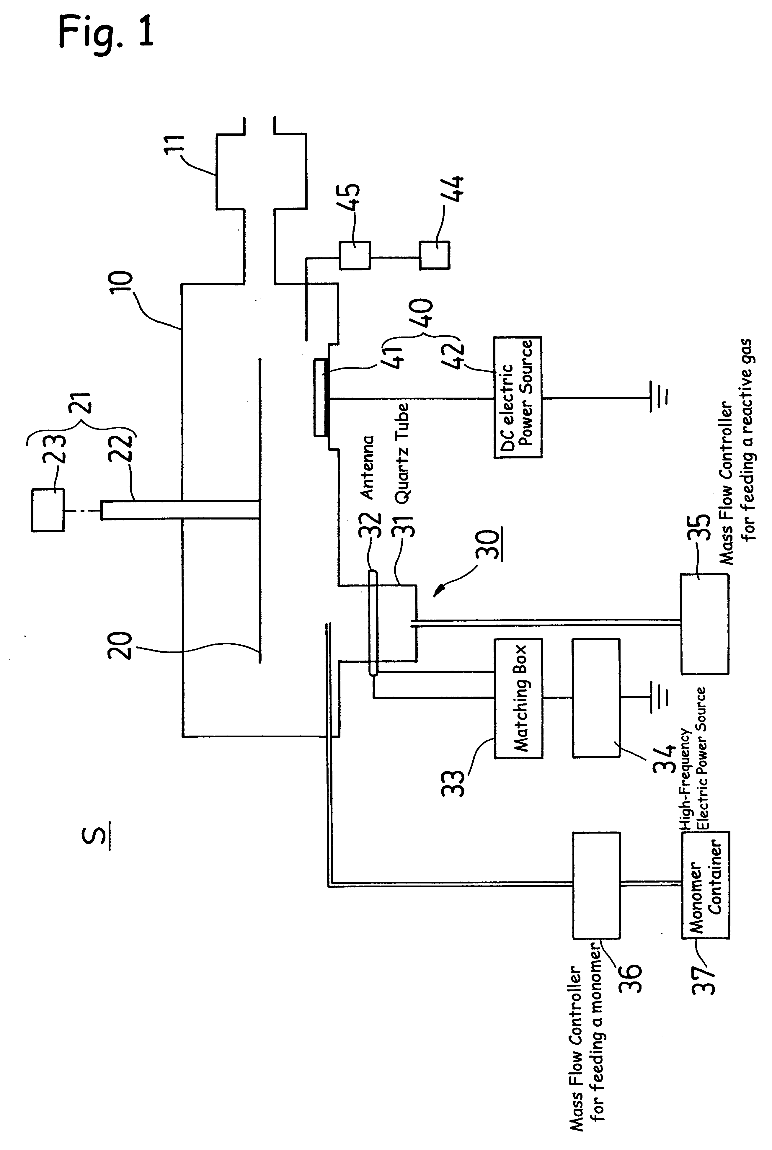
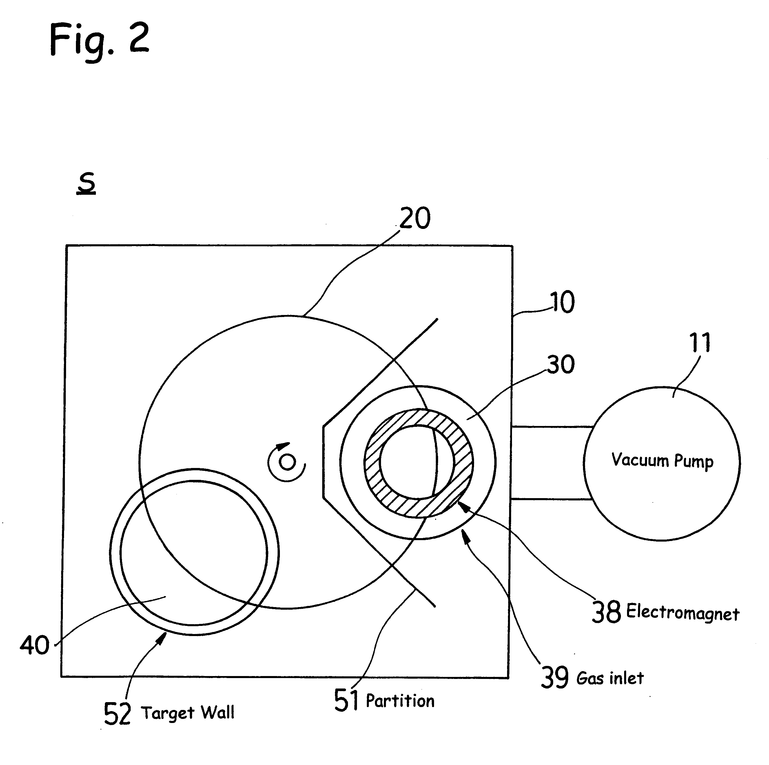
FIG. 1 is a schematic view of an embodiment of the apparatus for forming a thin film according to the present invention. The apparatus S for forming a thin film comprises, as primary components, a vacuum chamber 10, a holder 20, a plasma CVD apparatus 30, and a sputtering apparatus 40.

The apparatus S further comprises a vacuum pump 11, which is connected to the vacuum chamber 10. The holder 20, which can rotate, is disposed within the vacuum chamber 10 at an approximately center position of the chamber 10. In the chamber, the plasma CVD apparatus 30 and the sputtering apparatus 40 are disposed such that each opposingly faces the holder 20.

The apparatus S further comprises a rotating mechanism 21, which rotates the holder 20. The holder...


PUM

PropertyMeasurementUnit
Angleaaaaaaaaaa
Pressureaaaaaaaaaa
Pressureaaaaaaaaaa

Abstract

The present invention is drawn to an apparatus for forming a thin film. The apparatus includes a vacuum chamber; a vacuum apparatus connected to the vacuum chamber; a holder placed in the vacuum chamber, which holder holds a substrate and is rotated by means of a rotating mechanism; a plasma CVD apparatus; and a sputtering apparatus, wherein the plasma CVD apparatus and the sputtering apparatus are placed in a single vacuum chamber and a thin film having an medium refractive index is formed on the substrate held by the holder, by means of the plasma CVD apparatus and the sputtering apparatus. The method making use of such an apparatus is also disclosed.

Description

1. Field of the InventionThe present invention relates to an apparatus and method for forming a thin film. More particularly, the invention relates to an apparatus and method for forming, on a plastic substrate, a thin film having improved scratch resistance, an medium refractive index, and strong adhesion to the substrate.2. Background ArtConventionally, a variety of techniques have been known for forming a hard coating film on a plastic substrate.For example, an organic silicone coating film has been formed on a plastic lens by dipping to serve as a hard coating film. In order to adapt to a recent plastic lens per se having a high refractive index, a silicone coating film having a corresponding refractive index must be developed. Such a coating film is formed by use of an apparatus which enables provision of a specific refractive index in the formed coating film. Therefore, a facility for producing the coating film must disadvantageously be equipped with a plurality of dipping app...

Claims


Application Information

Patent Timeline
IPC IPC(8): C23C14/56C23C16/44C23C14/34G02B1/10C23C16/40C23C16/50C23C28/04G02B1/14
CPCC23C14/568H01J37/34C23C16/50H01J2237/32
Inventor MATSUMOTO, SHIGEHARUKIKUCHI, KAZUOSONG, YIZHOUSAKURAI, TAKESHISAISHO, SHINICHIRO
Owner SHINCRON KK
Learn More