Aerosol separator; and method

a technology of separator and aerosol, which is applied in the direction of separation process, filtration separation, combustion air/fuel air treatment, etc., can solve the problem of carrying substantial amounts of fine contaminan

Inactive Publication Date: 2001-09-18
DONALDSON CO INC
View PDF101 Cites 147 Cited by
  • Summary
  • Abstract
  • Description
  • Claims
  • Application Information

AI Technical Summary

Benefits of technology

Attention is directed to FIG. 4. When the filter element 70 is operably installed within the housing 52, the sealing portion 258 is compressed between and against the sealing surface 166 and the outer support liner 248 to form a radial seal 260 therebetween. As can be also seen in FIG. 4, the sealing portion 210 of the first end cap 202 is compressed between and against the sealing surface 128 and the outer support liner 248 to form radial seal 214 therebetween. The radial seals 214, 260 provide for the primary sealing system within the filter arrangement 50. The radial seals 214, 260 prevent unintended amo

Problems solved by technology

In addition, such gas streams also carry substantial am

Method used


Image

  • Aerosol separator; and method
  • Aerosol separator; and method
  • Aerosol separator; and method

Examples


Embodiment Construction

In this section, certain example materials useful for the embodiment of FIGS. 2-7 are described. A variety of materials may be used, other than those described herein.

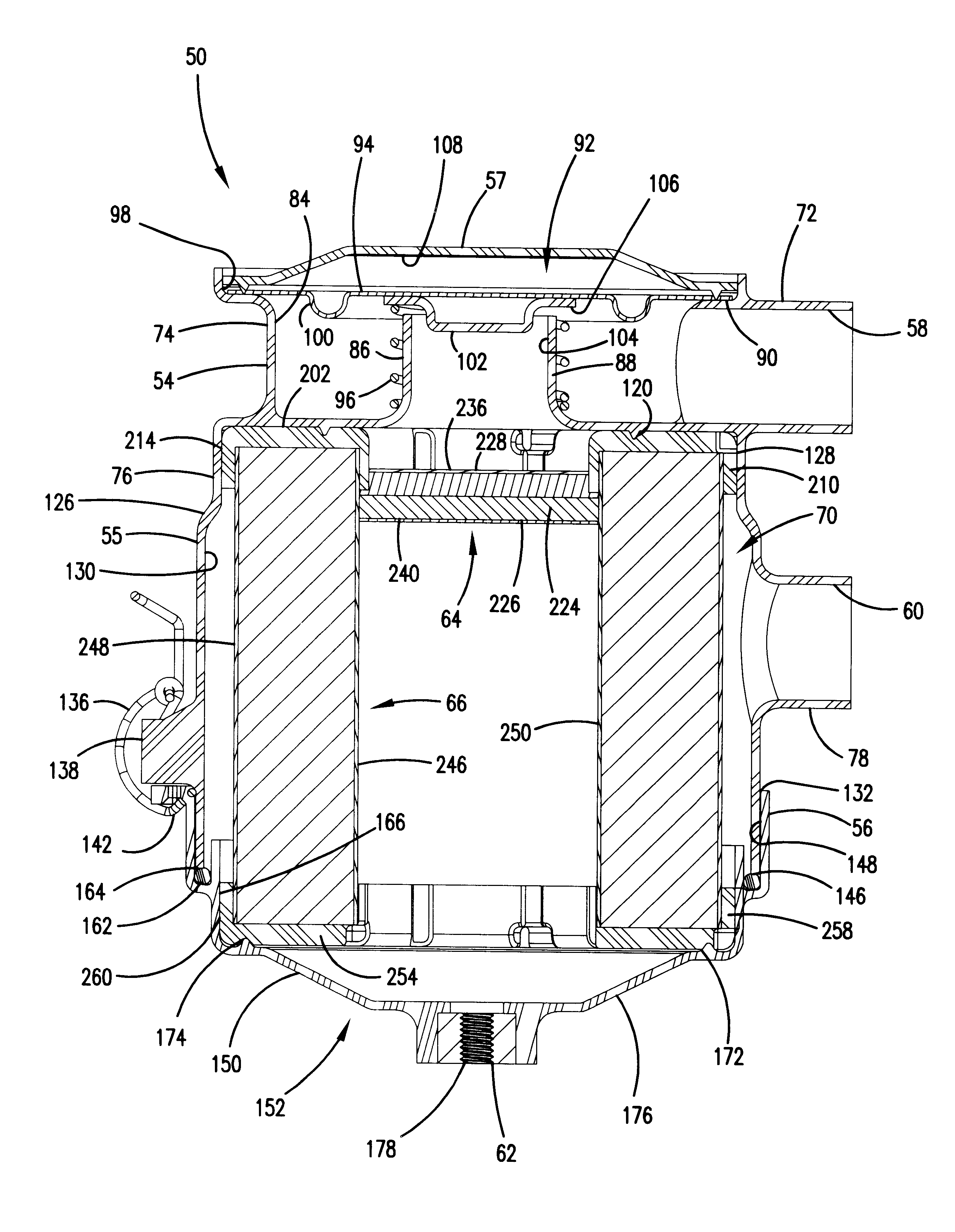
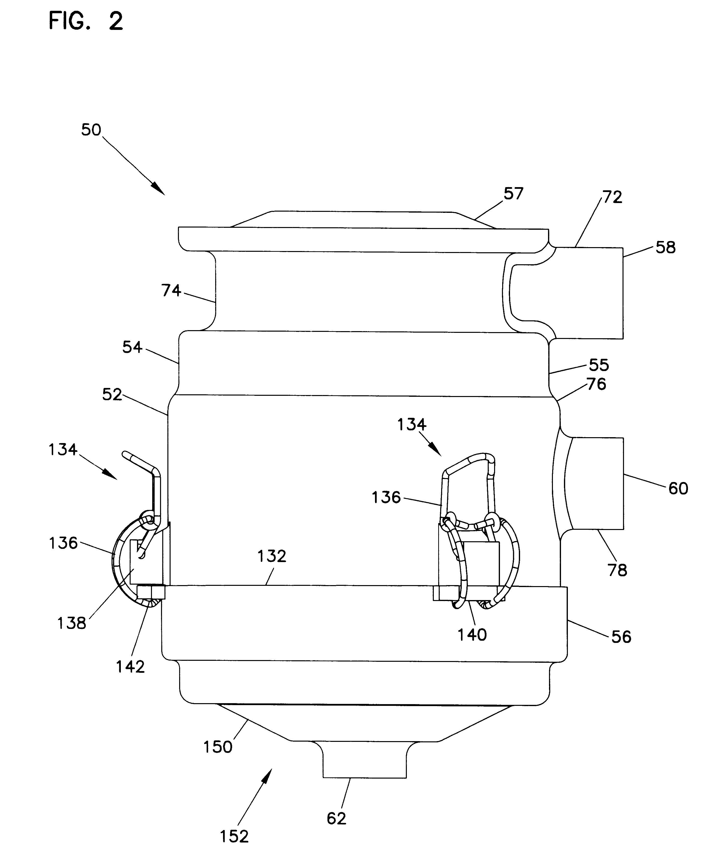
The housing 50 can be plastic, such as carbon filled nylon.

The media 224 of the coalescer 64 is generally non-pleated, non-cylindrical, polyester fibrous media having an average fiber diameter of less than about 18 microns, typically about 12.5 microns and a percent solidity, free state, of no greater than about 1.05%. The media 224 has an upstream, and a downstream exposed surface area of at least 1 in..sup.2, no greater than about 7 in..sup.2, and typically about 3-4 in..sup.2. The material has an average fiber diameter of 1.5 denier (about 12.5 micron), and a solidity in a free state of at least 0.85%. It has a weight of, typically, greater than about 3.1 ounces per square yard. Typically, it has a weight less than 3.8 ounces per square yard. Typical weights are within the range of 3.1-3.8 ounces per square yard (10...


PUM

PropertyMeasurementUnit
Fractionaaaaaaaaaa
Lengthaaaaaaaaaa
Flow rateaaaaaaaaaa

Abstract

An arrangement for separating a hydrophobic liquid phase from a gaseous stream includes a coalescer filter, a housing, a gas flow direction arrangement, and a liquid collection arrangement. The coalescer filter includes a non-woven media of fibers. The housing includes an interior having a gas flow inlet and a gas flow outlet. The liquid collection arrangement is positioned within the housing construction and is oriented for receiving liquid collected from the coalescer filter and drained therefrom.

Description

This disclosure relates to systems and methods for separating hydrophobic fluids (such as oils) which are entrained as aerosols, from gas streams (for example, air streams). Preferred arrangements also provide for filtration of other fine contaminants, for example carbon material, from the gas streams. Methods for conducting the separations are also provided.Certain gas streams, such as blow-by gases from diesel engines, carry substantial amounts of entrained oils therein, as aerosol. The majority of the oil droplets within the aerosol are generally within the size of 0.1-5.0 microns.In addition, such gas streams also carry substantial amounts of fine contaminant, such as carbon contaminants. Such contaminants generally have an average particle size of about 0.5-3.0 microns.In some systems, it is desirable to vent such gases to the atmosphere. In general, it is preferred that before the gases are vented to the atmosphere, they be cleaned of a substantial portion of the aerosol and / o...

Claims


Application Information

Patent Timeline
IPC IPC(8): B01D46/24B01D46/52B01D50/00F01M13/04F01M13/00B01D46/00B01D46/10
CPCB01D46/0004B01D46/003B01D46/0031B01D46/0049B01D46/008B01D46/2411B01D46/521B01D50/002F01M13/04B01D46/0023Y10S55/25B01D2265/028B01D2267/40B01D2271/02B01D2271/022F01M2013/0438Y10S55/30B01D46/88B01D46/62B01D50/20
Inventor GIESEKE, STEVEN SCOTTDUSHEK, ROBERT ALLENFINNERTY, CAROLYN J.
Owner DONALDSON CO INC
Why Eureka
Try Eureka